How to make a full-fledged power supply with an adjustable voltage range of 2.5-24 volts yourself, it's very simple, everyone can repeat without having any amateur radio experience behind them.
We will do it from an old computer power supply, TX or ATX without a difference, fortunately, over the years of the PC Era, every house has already accumulated a sufficient amount of old computer hardware and a power supply unit is probably also there, so the cost of homemade products will be insignificant, and for some masters it is equal to zero rubles ...
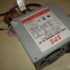
I got this AT block for alteration.

The more powerful you use the PSU, the better the result, my donor is only 250W with 10 amperes on the + 12v bus, but in fact, with a load of only 4 A, it can no longer cope, there is a complete drop in the output voltage.
See what is written on the case.

Therefore, see for yourself what current you plan to receive from your regulated power supply unit, and lay such a donor potential right away.
There are many options for finalizing a standard computer power supply unit, but they are all based on a change in the binding of the IC chip - TL494CN (its analogs DBL494, КА7500, IR3M02, A494, MV3759, M1114EU, МPC494C, etc.).

Fig. No. 0 Pinout of the TL494CN microcircuit and analogs.
Let's see some options execution of computer power supply circuits, perhaps one of them will be yours and it will become much easier to deal with the harness.
Scheme No. 1.
Let's get to work.
First you need to disassemble the PSU case, unscrew the four bolts, remove the cover and look inside.

We are looking for a microcircuit on the board from the list above, if there is none, then you can look for an option on the Internet for your IC.
In my case, a KA7500 microcircuit was found on the board, which means you can start studying the strapping and the location of parts that we do not need that need to be removed.

For the convenience of work, first completely unscrew the entire board and remove it from the case.

In the photo, the power connector is 220v.
We disconnect the power and the fan, solder or bite out the output wires so that they do not interfere with our understanding of the circuit, we will leave only the necessary ones, one yellow (+ 12v), black (common) and green * (start ON) if there is one.

There is no green wire in my AT block, so it starts up immediately when plugged into the outlet. If the ATX unit, then it must have a green wire, it must be soldered to the "common" one, and if you want to make a separate power button on the case, then just put the switch in the break of this wire.

Now you need to look at how many volts the output large capacitors cost, if less than 30v is written on them, then you need to replace them with similar ones, only with an operating voltage of at least 30 volts.

In the photo - black capacitors as a replacement for blue.
This is done because our modified unit will not give out +12 volts, but up to +24 volts, and without replacement, the capacitors will simply explode during the first test at 24v, after a few minutes of operation. When selecting a new electrolyte, it is not advisable to reduce the capacity; it is always recommended to increase it.
The most important part of the job.
We will remove all unnecessary in the harness IC494, and solder other denominations of the parts, so that the result is such a harness (Fig. №1).

Rice. No. 1 Change in the piping of the IC 494 microcircuit (revision scheme).
We will only need these legs of the microcircuit # 1, 2, 3, 4, 15 and 16, do not pay attention to the rest.

Rice. No. 2 Option revision on the example of scheme No. 1
Decoding of designations.

You need to do something like this, we find leg # 1 (where there is a point on the case) of the microcircuit and study what is connected to it, all circuits must be removed, disconnected. Depending on how the tracks will be located in your particular board modification and the parts are soldered, the optimal revision option is selected, it can be soldering and raising one leg of the part (breaking the chain) or it will be easier to cut the track with a knife. Having decided on an action plan, we begin the rework process according to the revision scheme.


In the photo - replacing the resistors with the desired value.

In the photo - by lifting the legs of unnecessary parts, we break the chains.
Some resistors that are already soldered into the strapping circuit can come up without replacing them, for example, we need to put a resistor at R = 2.7k connected to the "common", but there is already R = 3k connected to the "common", this suits us perfectly and we leave it there unchanged (example in Fig. №2, green resistors do not change).


On the picture- cut tracks and added new jumpers, write down the old denominations with a marker, you may need to restore everything back.
Thus, we view and redo all the circuits on the six legs of the microcircuit.
This was the most difficult point in the alteration.
We make voltage and current regulators.

We take variable resistors of 22k (voltage regulator) and 330Ω (current regulator), solder two 15cm wires to them, solder the other ends to the board according to the diagram (Fig. №1). Install on the front panel.
Voltage and current monitoring.
For control, we need a voltmeter (0-30v) and an ammeter (0-6A).

These devices can be purchased in Chinese online stores at the best price, my voltmeter cost me only 60 rubles delivery. (Voltmeter :)

I used my own ammeter, from the old stocks of the USSR.
IMPORTANT- there is a Current resistor (Current sensor) inside the device, which we need according to the diagram (Fig. №1), therefore, if you use an ammeter, then you do not need to install an additional Current resistor, you need to install it without an ammeter. Usually R Current is made homemade, a wire D = 0.5-0.6 mm is wound onto a 2-watt MLT resistance, a turn to a turn for the entire length, the ends are soldered to the resistance terminals, that's all.
Everyone will make the body of the device for themselves.
You can leave it completely metal by cutting holes for regulators and control devices. I used laminate trims, which are easier to drill and saw.
Good day to all! Today I want to present to your attention a Laboratory Power Supply (LPS). I think every novice radio amateur was faced with the problem of obtaining the necessary voltage for one or another of his homemade products, because each device requires a different voltage. I faced such a problem the other day. It was necessary to power a homemade amplifier, but the required voltage was not at hand. Well, this is not my first homemade product with which I have problems. So I got to work.
And so, we need:
-Casing (you can buy ready-made, or how can I take it from a computer power supply)
-Transformer with output voltages up to 30V and current up to 1.5 amperes (I took the trance more powerful since 1.5A is not enough for me)
-Simple set of radio parts:
-Diode bridge for 3A.
-Capacitor electrolytic 50V 2200mkf.
-Ceramic capacitor 0.1 microfarad (to smooth out the ripple more strongly).
-Circuit LM317 (in my case, 2 such microcircuits).
- 4.7kΩ variable resistor.
-Resistor 200 ohm 0.5W.
- Ceramic capacitor for 1mkf.
-Old analog tester (I used as a voltmeter).
-Textolite and iron chlorine (for etching the board).
-Terminals.
-Wires.
-Soldering accessories.
Getting started! I took the case from a computer Power Supply. We disassemble it and take out the insides and saw off the front panel (the one with which the wires come out) as in the photo.

We cut off the board fasteners on one side and bend them in such a way that we can then attach the front panel we made to them.


We choose a place for the transformer, drill holes in the lower part of the body and fix the transformer.

Now let's start collecting the board, first you need to etch it. We transfer the pre-printed board to the textolite.

And we throw in chlorine for 10-20 minutes. After we have etched holes and tinned the board.


We solder the elements according to the scheme.


We take the wires, assemble the circuit and pack everything into the case. IMPORTANT! (the microcircuit must be installed on the radiator, since under heavy loads it gets very hot and can fail). Here's what happened.

Now you need to get a voltmeter from an old tester. To do this, simply cut off the indicator itself from the plastic case.
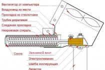
A rectifier is a device for converting AC voltage to DC voltage. It is one of the most common parts in electrical appliances, from hair dryers to all types of DC power supplies. There are different rectifier circuits and each of them, to a certain extent, copes with its task. In this article, we will talk about how to make a single phase rectifier and why you need one.
Definition
A rectifier is a device designed to convert alternating current into direct current. The word "constant" is not entirely correct, the fact is that at the output of the rectifier, in the sinusoidal alternating voltage circuit, in any case there will be an unstabilized ripple voltage. In simple words: constant in sign, but variable in magnitude.

There are two types of rectifiers:
Half-wave... It only rectifies one half-wave of the input voltage. Characterized by strong ripple and low voltage relative to the input.
Full-wave... Accordingly, two half-waves are straightened. Ripple is lower, the voltage is higher than at the input of the rectifier - these are two main characteristics.
What does stabilized and unstabilized voltage mean?
Stabilized is a voltage that does not change in magnitude regardless of either the load or the input voltage surges. For transformer power supplies, this is especially important, because the output voltage depends on the input voltage and differs from it at Ktransformation times.
Unregulated voltage - varies depending on power surges and load characteristics. With such a power supply, due to subsidence, the connected devices may malfunction or be completely inoperable and out of order.
Output voltage
The main values of the alternating voltage are the peak and rms value. When they say "there is a change in the 220V network" they mean the current voltage.

If we talk about the amplitude value, they mean how many volts from zero to the upper point of the half-wave of the sinusoid.

Omitting the theory and a number of formulas, we can say that 1.41 times less than the amplitude. Or:
The amplitude voltage in the 220V network is equal to:
The first scheme is more common. It consists of a diode bridge - interconnected by a "square", and a load is connected to its shoulders. The bridge rectifier is assembled according to the diagram below:


It can be connected directly to a 220V network, as is done in, or to the secondary windings of a network (50 Hz) transformer. Diode bridges according to this scheme can be assembled from discrete (separate) diodes or use a ready-made diode bridge assembly in a single package.

The second scheme - the midpoint rectifier cannot be connected directly to the mains. Its meaning is to use a mid-tapped transformer.

In essence, these are two half-wave rectifiers connected to the ends of the secondary winding, the load is connected with one contact to the connection point of the diodes, and the second to the tap from the middle of the windings.
Its advantage over the first circuit is the smaller number of semiconductor diodes. And the disadvantage is the use of a transformer with a midpoint, or, as it is also called, a tap from the middle. They are less common than conventional secondary winding transformers without taps.
Ripple smoothing
Ripple voltage supply is unacceptable for a number of consumers, for example, light sources and audio equipment. Moreover, the permissible pulsations of light are regulated in state and industry regulations.
To smooth out ripples, they use a parallel installed capacitor, an LC filter, a variety of P- and G-filters ...

But the most common and simplest option is a capacitor installed in parallel with the load. Its disadvantage is that to reduce ripple at a very powerful load, you will have to install very large capacitors - tens of thousands of microfarads.
Its principle of operation is that the capacitor is charged, its voltage reaches its amplitude, the supply voltage after the point of maximum amplitude begins to decrease, from that moment the load is powered by the capacitor. The capacitor is discharged depending on the load resistance (or its equivalent resistance if it is not resistive). The larger the capacitance of the capacitor, the smaller the ripple will be, when compared with a capacitor with a lower capacitance connected to the same load.
In simple words: the slower the capacitor discharges, the less ripple.
The discharge rate of the capacitor depends on the current consumed by the load. It can be determined by the formula for the time constant:
where R is the load resistance and C is the capacitance of the smoothing capacitor.
Thus, from a fully charged state to a fully discharged state, the capacitor will be discharged in 3-5 t. Charges at the same rate if the charge is through a resistor, so in our case it doesn't matter.
Hence it follows that in order to achieve an acceptable level of ripple (it is determined by the load requirements for the power source), a capacitance is needed, which will be discharged in a time several times longer than t. Since the resistances of most loads are relatively small, a large capacitance is needed, therefore, in order to smooth out ripples at the output of the rectifier, they are used, they are also called polar or polarized.
Please note that it is highly discouraged to confuse the polarity of an electrolytic capacitor, because this is fraught with its failure and even an explosion. Modern capacitors are protected from explosion - they have a cross-shaped stamp on the top cover, along which the case is simply cracked. But a stream of smoke will come out of the condenser, it will be bad if it gets into your eyes.
The calculation of the capacity is based on what ripple factor must be provided. In simple terms, the ripple coefficient shows by what percentage the voltage sags (pulsates).
C = 3200 * In / Un * Kp,
Where Iн - load current, Un - load voltage, Kn - ripple coefficient.
For most types of equipment, the ripple factor is taken as 0.01-0.001. Additionally, it is advisable to install as large a capacity as possible to filter out high-frequency interference.
How to make a DIY power supply?
 The simplest DC power supply consists of three elements:
1. Transformer;
3. Condenser.

It is an unregulated DC power supply with a smoothing capacitor. The voltage at its output is greater than the alternating voltage of the secondary winding. This means that if you have a 220/12 transformer (primary at 220V, and secondary at 12V), then at the output you will receive a 15-17V constant. This value depends on the capacitance of the smoothing capacitor. This circuit can be used to power any load, if it does not matter for it, then the voltage can "float" when the supply voltage changes.
A capacitor has two main characteristics - capacitance and voltage. We figured out how to select the capacity, but not with the selection of voltage. The capacitor voltage must exceed the peak voltage at the output of the rectifier by at least half. If the actual voltage on the capacitor plates exceeds the nominal, there is a high probability of its failure.
Old Soviet capacitors were made with a good voltage margin, but now everyone uses cheap electrolytes from China, where at best there is a small margin, and at worst it will not withstand the specified nominal voltage. So don't skimp on reliability.


The stabilized power supply unit differs from the previous one only by the presence of a voltage (or current) stabilizer. The simplest option is to use L78xx or others, such as the domestic KREN.
So you can get any voltage, the only condition when using such stabilizers is that the voltage before the stabilizer must exceed the stabilized (output) value by at least 1.5V. Consider what is written in the datasheet of the 12V stabilizer L7812:

The input voltage should not exceed 35V for stabilizers from 5 to 12V, and 40V for stabilizers for 20-24V.

The input voltage must exceed the output voltage by 2-2.5V.
Those. for a stabilized 12V power supply with a stabilizer of the L7812 series, it is necessary that the rectified voltage lies in the range of 14.5-35V, in order to avoid drawdowns, it will be an ideal solution to use a transformer with a 12V secondary winding.
But the output current is quite modest - only 1.5A, it can be amplified using a pass-through transistor. If you have, you can use this scheme:

It shows only the connection of a linear stabilizer. The "left" part of the circuit with a transformer and a rectifier is omitted.
If you have NPN transistors such as KT803 / KT805 / KT808, then this one will do:

It is worth noting that in the second circuit, the output voltage will be 0.6V less than the stabilization voltage - this is the drop at the emitter-base junction, we wrote about this in more detail. To compensate for this drop, a diode D1 was introduced into the circuit.
It is possible to install two linear stabilizers in parallel, but it is not necessary! Due to possible manufacturing deviations, the load will be unevenly distributed and one of them may burn out because of this.
Install both the transistor and the linear regulator on the heatsink, preferably on different heatsinks. They get very hot.
Regulated power supplies
The simplest regulated power supply can be made with an adjustable linear stabilizer LM317, its current is also up to 1.5 A, you can amplify the circuit with a pass transistor, as described above.

Here is a more visual diagram for assembling a regulated power supply.
With a thyristor regulator in the primary winding, in fact the same regulated power supply.

By the way, the welding current is also regulated with a similar scheme:

Conclusion
A rectifier is used in power supplies to generate DC from AC. Without his participation, it will not be possible to power a DC load, for example, an LED strip or a radio receiver.
They are also used in a variety of chargers for car batteries, there are a number of circuits using a transformer with a group of taps from the primary winding, which are switched by a wafer switch, and only a diode bridge is installed in the secondary winding. The switch is installed on the high voltage side, since the current is several times lower there and its contacts will not burn from this.
According to the diagrams from the article, you can assemble a simple power supply unit both for permanent work with some device, and for testing your electronic homemade products.
The circuits do not differ in high efficiency, but they give out a stabilized voltage without special ripples, you should check the capacitances of the capacitors and calculate for a specific load. They are perfect for low-power audio amplifiers, and will not create additional background. The adjustable power supply will be useful for motorists and auto electricians to test the alternator voltage regulator relay.
An adjustable power supply is used in all areas of electronics, and if it is improved with short-circuit protection or a current stabilizer on two transistors, then you will get an almost complete laboratory power supply.
This article is intended for people who can quickly distinguish a transistor from a diode, know what a soldering iron is for and which side to hold it on, and finally came to the understanding that without a laboratory power supply, their life no longer makes sense ...
This scheme was sent to us by a person under the nickname: Loogin.
All images are reduced in size, to view in full size, left-click on the image
Here I will try to do it in as much detail as possible - step by step to tell you how to do it with minimal costs. Surely everyone has at least one power supply unit lying under their feet after upgrades of home hardware. Of course, you will have to buy something, but these sacrifices will be small and most likely justified by the end result - this is, as a rule, about 22V and 14A ceiling. Personally, I invested $ 10. Of course, if you collect everything from the "zero" position, then you need to be ready to shell out about $ 10-15 more to buy the power supply itself, wires, potentiometers, knobs and other loose products. But, usually - everyone has such rubbish in bulk. There is also a nuance - you have to work a little with your hands, so they should be "no displacement" J, and something like this may work for you:
First, you need by any means to get an unnecessary but serviceable ATX power supply unit with a power> 250W. One of the most popular schemes is Power Master FA-5-2:

I will describe a detailed sequence of actions for this particular scheme, but they are all valid for other options.
So, at the first stage, you need to prepare a BP donor:
- We remove the diode D29 (you can just raise one leg)
- Remove jumper J13, find it in the circuit and on the board (you can use wire cutters)
- The PS ON jumper to ground must be in place.
- We turn on the PB only for a short time, since the voltage at the inputs will be maximum (about 20-24V) Actually, this is what we want to see ...
Don't forget about the 16V output electrolytes. They may heat up a little. Considering that they are most likely "swollen", they still have to be sent to the swamp, it's not a pity. Remove the wires, they interfere, and only GND will be used and + 12V will then solder them back.

5. Remove the 3.3 volt part: R32, Q5, R35, R34, IC2, C22, C21:

6.
Remove 5V: Schottky assembly HS2, C17, C18, R28, you can also "type choke" L5
7.
Remove -12V -5V: D13-D16, D17, C20, R30, C19, R29

8.
We change the bad ones: replace C11, C12 (preferably with a large capacity C11 - 1000uF, C12 - 470uF)
9.
We change the inappropriate components: C16 (preferably at 3300uF x 35V like mine, well, at least 2200uF x 35V is required!) And I advise you to replace the resistor R27 with a more powerful one, for example 2W and take 360-560 Ohm resistance.

We look at my board and repeat:
10.
We remove everything from the legs TL494 1,2,3 for this we remove the resistors: R49-51 (release the 1st leg), R52-54 (... 2nd leg), C26, J11 (... 3rd leg)
11.
I do not know why, but R38 was chopped off by someone J I recommend that you chop it down too. It participates in voltage feedback and is parallel to R37. Actually R37 can be cut too.

12. we separate the 15th and 16th legs of the microcircuit from "all the rest": for this we make 3 cuts of the existing tracks and to the 14th leg we restore the connection with a black jumper, as shown in my photo.

13.
Now we solder the loop for the regulator board to the points according to the diagram, I used the holes from the soldered resistors, but by the 14th and 15th I had to peel off the varnish and drill the holes, in the photo above.
14.
The core of loop No. 7 (regulator power supply) can be taken from the + 17V TL-ki power supply, in the area of the jumper, more precisely from it J10. Drill a hole in the track, clean the varnish and go there! It is better to drill from the print side.

It was all, as the saying goes: "minimal revision" to save time. If time is not critical, then you can simply bring the circuit to the following state:

I would also advise you to change the high-voltage conduits at the input (C1, C2) They are small in capacity and are probably already pretty dry. 680uF x 200V would normally be there. Plus, it's nice to slightly alter the L3 group stabilization choke, or use 5-volt windings, connecting them in series, or remove everything altogether and wind about 30 turns with a new enamel wire with a total cross section of 3-4mm 2.
To power the fan, you need to "prepare" 12V for it. I got out this way: Where there used to be a field-effect transistor for the formation of 3.3V, you can "settle" a 12-volt KREN-ku (KREN8B or 7812 imported analog). Of course, there is no way to do without cutting tracks and adding wires. In the end, it turned out, in general, even "nothing":


The photo shows how everything harmoniously coexisted in the new quality, even the fan connector fit well and the rewound choke turned out to be quite good.
Now the regulator. To simplify the task with different shunts there, we do this: we buy ready-made ammeter and voltmeter in China, or in the local market (you can probably find them there from dealers). You can buy a combined one. But, we must not forget that their current ceiling is 10A! Therefore, in the regulator circuit, you will have to limit the current limit at this point. Here I will describe an option for individual devices without current regulation and limited to a maximum of 10A. Regulator circuit:

To adjust the current limiting, instead of R7 and R8, put a 10kΩ variable resistor, just like R9. Then it will be possible to use the all-round. Also worth paying attention to is the R5. In this case, its resistance is 5.6kΩ, because our ammeter has a 50mΩ shunt. For other variants R5 = 280 / R shunt. Since we took a voltmeter one of the cheapest, so it needs to be modified a little so that it can measure voltages from 0V, and not from 4.5V as the manufacturer did. The whole rework is to separate the supply and measurement circuits by removing the diode D1. We solder the wire there - this is the + V power supply. The measured part remained unchanged.

The layout of the regulator board is shown below. The image for the laser-ironing method of manufacturing comes in a separate Regulator.bmp file with a resolution of 300dpi. Also in the archive there are files for editing in EAGLE. The last off. the version can be downloaded here: www.cadsoftusa.com. There is a lot of information on the Internet about this editor.


Then we fasten the finished board to the ceiling of the case through insulating spacers, for example, cut from a spent chupa-chups stick with a height of 5-6 mm. Well, do not forget to pre-make all the necessary cutouts for measuring and other devices.


Pre-assemble and test under load:


We are just looking at the correspondence of the readings of various Chinese devices. And below with a "normal" load. This is a car main light bulb. As you can see - almost 75W is available. In this case, do not forget to shove an oscilloscope there, and see the ripple of about 50mV. If there is more, then we recall the "large" electrolytes on the high side with a capacity of 220uF and immediately forget after replacing them with normal ones with a capacity of 680uF, for example.

In principle, we can stop at this, but in order to give a more pleasant look to the device, well, so that it does not look 100% homemade, we do the following: we leave our den, go up to the floor above and remove a useless sign from the first door we come across.
As you can see, someone has already been here before us.

In general, we quietly do this dirty business and begin to work with files of different styles and at the same time master AutoCad.


Then we sharpen a piece of a three-quarter pipe on emery and cut out the legs from a fairly soft rubber of the required thickness and superglue the legs.

|

|
As a result, we get a fairly decent device:

Several points should be noted. The most important thing is not to forget that the GND of the power supply and the output circuit must not be connected., therefore, it is necessary to exclude the connection between the case and the GND of the power supply unit. For convenience, it is advisable to take out the fuse, as in my photo. Well, try to restore the missing elements of the input filter as much as possible, most likely the source does not have them at all.
Here are a couple more options for such devices:

On the left is a 2-storey ATX case with an all-round, and on the right is a heavily altered old AT case from a computer.
It took one day to develop this power supply, on the same day it was implemented, and the whole process was filmed on a video camera. A few words about the scheme. This is a stabilized power supply with output voltage regulation and current limiting. Schematic features allow you to throw off the minimum edge of the output voltage to 0.6 Volts, and the minimum output current in the region of 10mA.
Despite the prostate design, even good laboratory power supplies with a cost of 5-6 thousand rubles are inferior to this power supply! The maximum output current of the circuit is 14Amps, the maximum output voltage is up to 40V - no longer worth it.
Quite smooth current limiting and voltage regulation. The unit also has a fixed protection against short circuits, by the way - the current protection can also be set (almost all industrial designs are deprived of this function), for example, if you need the protection to operate at currents up to 1 Ampere, then you just need to adjust such a current using regulator for setting the operating current. The maximum current is 14Amps, but this is not the limit either.


As a current sensor, I used several resistors of 5 watts 0.39 Ohm connected in parallel, but their value can be changed based on the required protection current, for example - if you plan a power supply with a maximum current of no more than 1 Ampere, then the value of this resistor is in the region of 1 Ohm at power 3W.
In case of short circuits, the voltage drop across the current sensor is sufficient to trigger the BD140 transistor.When it is opened, the lower transistor, BD139, is also triggered, through the open transition of which power is supplied to the relay coil, as a result of which the relay is triggered and the working contact is opened (at the circuit output). The circuit can be in this state for as long as necessary. Together with the protection, the protection indicator is also triggered. In order to remove the block from protection, you need to press and lower the S2 button according to the diagram.
Protection relay with a 24 Volt coil with an allowable current of 16-20 and more Amperes.
The power switches in my case are my favorite KT8101 installed on the heat sink (you do not need to additionally isolate the transistors, since the key collectors are common). You can replace the transistors with 2SC5200 - a complete imported analogue or with KT819 with the GM index (iron), if you wish, you can also use - KT803, KT808, KT805 (in iron cases), but the maximum recoil current will be no more than 8-10 Amperes. If the unit is needed with a current of no more than 5 Amperes, then one of the power transistors can be removed.
Low-power transistors such as BD139 can be replaced with a full analogue - KT815G, (you can also - KT817, 805), BD140 - with KT816G (you can also KT814).
Low-power transistors do not need to be installed on heat sinks.
In fact, only the control (regulation) and protection (working unit) scheme is presented. As a power supply, I used modified computer power supplies (connected in series), but you can use any network transformer with a power of 300-400 watts, 30-40 Volts in the secondary winding, a winding current of 10-15 Amperes - this is ideal, but you can use transformers and less power.
Diode bridge - any, with a current of at least 15 Amperes, the voltage is not important. You can use ready-made bridges, they cost no more than 100 rubles.
For 2 months, more than 10 such power supplies were assembled and sold - no complaints. For myself, I assembled exactly such a power supply unit, and as soon as I did not torment it, it was indestructible, powerful and very convenient for any business.
If there are those who want to become the owner of such a power supply unit, I can make it on order, contact me at This email address is being protected from spambots. You need JavaScript enabled to view it., the rest will be told by video tutorials on assembly.