If the body is motionless, then this body is in balance. Many bodies rest, despite the fact that they are acted upon by forces from other bodies. These are various structures, stones, cars, parts of mechanisms, bridges and many other bodies. The problem of studying the conditions of equilibrium of bodies is of great practical importance for mechanical engineering, construction, instrument making and other areas of technology.
All real bodies, under the influence of forces applied to them from other bodies, change their shape and size, that is, they are deformed. The amount of deformation depends on many factors: the material of the body, its shape, forces applied to it. Deformations can be so small that they can only be detected with the help of special instruments.
Deformations can be large and easy to spot, such as stretching a spring or rubber cord, bending a wooden board or a thin metal ruler.
Sometimes the actions of forces cause significant deformations of the body, in this case, in fact, after the application of forces, we will be dealing with a body that has completely new geometric dimensions and shape. It will also be necessary to determine the equilibrium conditions for this new deformed body. Such problems associated with calculating the deformations of bodies are usually very difficult.
Quite often, in real life situations, the deformations are very small, while the body remains in balance. In such cases, deformations can be neglected and the situation can be considered as if the bodies were non-deformable, that is, absolutely rigid. An absolutely rigid body in mechanics is a model of a real body in which the distance between particles does not change, no matter what influences this body is subjected to. It should be understood that absolutely rigid bodies do not exist in nature, but in some cases we can consider a real body to be absolutely rigid.
For example, a reinforced concrete floor slab of a house can be considered an absolutely solid body when there is a very heavy cabinet on it. The gravity of the cabinet acts on the stove, and the stove bends, but this deformation will be so small that it can only be detected with accurate instruments. Therefore, in this situation, we can neglect the deformation and consider the plate as an absolutely solid body.
Having found out the equilibrium conditions of an absolutely rigid body, we find out the equilibrium conditions for real bodies in situations where their deformations can be neglected.
Statics is a branch of mechanics in which the conditions of equilibrium of absolutely rigid bodies are studied.
In statics, the size and shape of bodies are taken into account, and all bodies under consideration are considered absolutely rigid. Statics can be considered as a special case of dynamics, since the immobility of bodies, when forces act on them, is a special case of motion with zero speed.
Deformations occurring in the body are studied in the applied branches of mechanics (theory of elasticity, resistance of materials). In what follows, for brevity, an absolutely rigid body will be called a rigid body, or simply a body.
Let's find out the conditions of equilibrium of any body. For this we use Newton's laws. To simplify our task, let's mentally divide the whole body into a large number of small parts, each of which can be considered as a material point. The whole body consists of many elements, some of which are shown in the figure. The forces that act on a given body from other bodies are external forces. Internal forces are the forces with which the elements act on each other. Force F1,2 is the force acting on element 1 from the side of element 2. Force F2,1 is applied to element 2 by element 1. These are internal forces; these also include the forces F1.3 and F3.1, F2.3 and F3.2.
Forces F1, F2, F3 are the geometric sum of all external forces acting on elements 1, 2, 3. Forces F1 prime, F2 prime, F3 prime are the geometric sum of internal forces applied to elements 1, 2, 3.
The acceleration of each element of the body is zero because the body is at rest. Hence, according to Newton's second law, the geometric sum of all internal and external forces acting on the element is also equal to zero.
For the balance of a body, it is necessary and sufficient that the geometric sum of all external and internal forces acting on each element of this body is equal to zero.
What conditions must external forces acting on a rigid body satisfy in order for it to be at rest? To do this, add up the equations. Equality turns out to be zero.
In the first brackets of this equality is written the vector sum of all external forces acting on the body, and in the second brackets - the vector sum of all internal forces applied to the elements of this body. We have already found out, using Newton's third law, that the vector sum of all internal forces of the system is equal to zero, because any internal force corresponds to a force equal to it in modulus and opposite in direction.
Consequently, in the resulting equality, only the geometric sum of external forces remains, which have an effect on the body.
This equality is a prerequisite for the balance of the material point. If we apply it to a rigid body, then this equality is called the first condition for its equilibrium.
In the event that a rigid body is in equilibrium, then the geometric sum of external forces applied to it is equal to zero.
Considering the fact that several external forces can be applied to one elements of the body at once, and external forces may not act at all on other elements, the number of all external forces does not necessarily have to be equal to the number of all elements.
If the sum of the external forces is equal to zero, then the sum of the projections of these forces on the coordinate axes is also equal to zero. In particular, for the projections of external forces on the OX axis, it can be written that the sum of the projections on the OX axis of external forces is zero. In a similar way, the equation for the projections of forces on the OY and OZ axes can be written.
On the basis of the equilibrium condition for any element of the body, the first equilibrium condition for a rigid body is derived.
The body is at rest (or moves uniformly and rectilinearly) if the vector sum of all the forces acting on it is equal to zero. The forces are said to counterbalance each other. When we are dealing with a body of a certain geometric shape, when calculating the resultant force, all forces can be applied to the center of mass of the body.
Equilibrium condition for bodies
For a body that does not rotate to be in equilibrium, it is necessary that the resultant of all forces acting on it be equal to zero.
F → = F 1 → + F 2 → +. ... + F n → = 0.
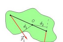
The figure above shows the equilibrium of a rigid body. The bar is in a state of equilibrium under the influence of three forces acting on it. The lines of action of the forces F 1 → and F 2 → intersect at the point O. The point of application of the force of gravity is the center of mass of the body C. These points lie on one straight line, and when calculating the resultant force F 1 →, F 2 → and m g → are reduced to point C.
The condition of equality to zero of the resultant of all forces is not enough if the body can rotate around some axis.
The shoulder of the force d is the length of the perpendicular drawn from the line of action of the force to the point of its application. The moment of force M is the product of the shoulder of the force by its modulus.
The moment of force tends to rotate the body around the axis. Those moments that rotate the body counterclockwise are considered positive. The unit of measurement of the moment of force in the international system SI is 1 Nyutonmetr.
Definition. Rule of the Moments
If the algebraic sum of all the moments applied to the body relative to the fixed axis of rotation is zero, then the body is in equilibrium.
M 1 + M 2 +. ... + M n = 0

Important!
In the general case, for the balance of bodies, two conditions must be met: equality to zero of the resultant force and observance of the rule of moments.
There are different types of balance in mechanics. So, they distinguish between stable and unstable, as well as indifferent equilibrium.

A typical example of indifferent equilibrium is a rolling wheel (or ball), which, if stopped at any point, is in a state of equilibrium.
Stable equilibrium is such a balance of a body when, with its small deviations, forces or moments of forces arise that tend to return the body to an equilibrium state.
Unstable equilibrium is a state of equilibrium, with a small deviation from which the forces and moments of forces tend to unbalance the body even more.

In the picture above, the position of the ball (1) is an indifferent equilibrium, (2) is an unstable equilibrium, (3) is a stable equilibrium.
A body with a fixed axis of rotation can be in any of the described equilibrium positions. If the axis of rotation passes through the center of mass, an indifferent equilibrium arises. In a stable and unstable equilibrium, the center of mass is located on a vertical line that passes through the axis of rotation. When the center of mass is below the axis of rotation, equilibrium is stable. Otherwise, the opposite is true.

A special case of balance is the balance of the body on a support. In this case, the elastic force is distributed over the entire base of the body, and does not pass through one point. The body is at rest in equilibrium when a vertical line drawn through the center of mass intersects the support area. Otherwise, if the line from the center of mass does not fall into the contour formed by the lines connecting the pivot points, the body overturns.
An example of body balance on a support is the famous Leaning Tower of Pisa. According to legend, Galileo Galilei dropped balls from it when he conducted his experiments to study the free fall of bodies.

A line drawn from the center of mass of the tower intersects the base approximately 2.3 m from its center.
If you notice an error in the text, please select it and press Ctrl + Enter
All the forces acting on a material point, applied at one point. The resulting force is defined as the geometric sum of all forces acting on a material point. If the resulting force is zero, then according to the 2nd law Newton the acceleration of a material point is equal to zero, the speed is constant or equal to zero, the material point is in a state of equilibrium.
Equilibrium condition of a material point: . (6.1)
A much more important question in statics is the question of the balance of an extended body, since in practice one has to deal with just such bodies. It is clear that for the balance of the body it is necessary that the resulting force acting on the body be equal to zero. But the fulfillment of this condition is not enough. Consider a horizontally located rod that can rotate about a horizontal axis O(fig. 6.2). The rod is acted upon by: the force of gravity, the reaction force of the axis, two external forces and, equal in magnitude and opposite in direction. The resultant of these forces is zero:
however, our practical experience tells us that the rod will start to rotate, i.e. will not be in a state of equilibrium. Please note that the moments of forces and about the axis O are equal to zero, the moments of forces and are not equal to zero and both are positive, the forces try to rotate the rod clockwise about the axis O.
Figure 6.3 forces are both equal in magnitude and directed in the same way. The resultant of all forces acting on the rod is equal to zero (in this case, the force is greater than in the first case, it balances the resultant of three forces -, and). The resulting moment of all forces is zero, the rod is in equilibrium. We come to the conclusion that two conditions must be met for body balance.
Equilibrium conditions for an extended body:
Let us write down important rules that can be used when considering the conditions of body balance.
1. The vectors of forces applied to the body can be moved along the line of their action. The resulting force and the resulting torque do not change.
2. The second equilibrium condition is fulfilled with respect to any axis of rotation. It is convenient to choose such an axis of rotation with respect to which equation (6.3) will be the simplest. For example, about the axis O in fig. 6.2 moments of forces and are equal to zero.
Stable balance... In stable equilibrium, the potential energy of the body is minimal. When the body is displaced from a position of stable equilibrium, the potential energy increases, a resultant force arises, directed towards the equilibrium position.
Unstable equilibrium... When the body is displaced from an unstable equilibrium position, the potential energy decreases, and a resultant force arises, directed from the equilibrium position.
Body center of gravity- the point of application of the resultant of all gravity forces acting on individual elements of the body.
Equilibrium sign... The body is in balance if the vertical line passing through the center of gravity intersects the body's support area.


 Back forward
Attention! Slide previews are for informational purposes only and may not represent all the presentation options. If you are interested in this work, please download the full version.
Lesson objectives: Study the state of balance of bodies, get acquainted with different types of balance; find out the conditions under which the body is in equilibrium.
Lesson Objectives:
- Educational: Study two conditions of equilibrium, types of equilibrium (stable, unstable, indifferent). Find out under what conditions the bodies are more stable.
- Developing: Promote the development of a cognitive interest in physics. Development of skills to compare, generalize, highlight the main thing, draw conclusions.
- Educational: To educate attention, the ability to express their point of view and defend it, to develop the communication skills of students.
Lesson type: a lesson in learning new material with computer support.
Equipment:
- Disk "Work and Power" from "Electronic Lessons and Tests.
- Equilibrium conditions table.
- Tilting prism with a plumb line.
- Geometric bodies: cylinder, cube, cone, etc.
- Computer, multimedia projector, interactive whiteboard or screen.
- Presentation.
During the classes
Today in the lesson we will learn why the crane does not fall, why the toy "Vanka-vstanka" always returns to its original state, why the Leaning Tower of Pisa does not fall?
I. Repetition and actualization of knowledge.
- Formulate Newton's first law. What state does the law say?
- What question does Newton's second law answer? Formula and wording.
- What question does Newton's third law answer? Formula and wording.
- What is called the resultant force? How is it located?
- From the disc "Movement and interaction of bodies" complete task number 9 "Resultant forces with different directions" (the rule of adding vectors (2, 3 exercises)).
II. Learning new material.
1. What is called balance?
Equilibrium is a state of calm.
2. Equilibrium conditions.(slide 2)
a) When is the body at rest? What law does this follow?
The first equilibrium condition: The body is in equilibrium if the geometric sum of the external forces applied to the body is equal to zero. ∑F = 0
b) Let two equal forces act on the board, as shown in the figure.

Will she be in balance? (No, she will turn)
Only the central point is at rest, and the rest are moving. This means that for the body to be in equilibrium, it is necessary that the sum of all the forces acting on each element be equal to 0.
Second equilibrium condition: The sum of the moments of forces acting clockwise must equal the sum of the moments of forces acting counterclockwise.
∑ M clockwise = ∑ M counterclockwise
Moment of force: M = F L
L - shoulder of force - the shortest distance from the fulcrum to the line of action of the force.
3. The center of gravity of the body and its location.(slide 4)
Body center of gravity- this is the point through which the resultant of all parallel gravity forces acting on individual elements of the body passes (for any position of the body in space).
Find the center of gravity of the following shapes:

4. Types of balance.
a) (slides 5-8)


Output: Equilibrium is stable if, with a small deviation from the equilibrium position, there is a force tending to return it to this position.
Stable is the position in which its potential energy is minimal. (slide 9)
b) Stability of bodies located on the fulcrum or on the line of support.(slides 10-17)

Output: For the stability of a body located on one point or line of support, it is necessary that the center of gravity be below the point (line) of support.
c) Stability of bodies on a flat surface.
(slide 18)
1) Support surface- it is not always the surface that is in contact with the body (but the one that is bounded by the lines connecting the legs of the table, tripods)

2) Analysis of the slide from "Electronic lessons and tests", disc "Work and power", lesson "Types of balance".
Picture 1.
- How are stools different? (Support area)
- Which one is more stable? (With a larger area)
- How are stools different? (The location of the center of gravity)
- Which one is the most stable? (With lower center of gravity)
- Why? (Since it can be tilted to a larger angle without overturning)
3) Experiment with a deflecting prism
- We put a prism with a plumb line on the board and begin to gradually raise it over one edge. What do we see?
- As long as the plumb line crosses the surface bounded by the support, balance is maintained. But as soon as the vertical, passing through the center of gravity, begins to go beyond the boundaries of the support surface, the stack overturns.
Parsing slides 19-22.

Conclusions:
- The body with a larger support area is stable.
- Of two bodies of the same area, the one with the lower center of gravity is stable. it can be tilted without overturning at a large angle.
Parsing slides 23-25.

Which ships are the most stable? Why? (For which the cargo is located in the holds and not on the deck)

Which cars are the most resilient? Why? (To increase the stability of cars on bends, the roadbed is tilted towards the bend.)
Conclusions: Equilibrium can be stable, unstable, indifferent. The greater the support area and the lower the center of gravity, the greater the stability of the bodies.
III. Application of knowledge about the stability of bodies.
- What specialties are most needed to know about the balance of bodies?
- Designers and constructors of various structures (high-rise buildings, bridges, television towers, etc.)
- Circus artists.
- Drivers and other professionals.
(slides 28-30)
- Why does Vanka-Vstanka return to the balance position at any tilt of the toy?
- Why is the Leaning Tower of Pisa tilted and not falling?
- How do cyclists and motorcyclists keep their balance?
Conclusions from the lesson:
- There are three types of balance: stable, unstable, indifferent.
- The position of the body is stable, in which its potential energy is minimal.
- The stability of bodies on a flat surface is the greater, the larger the support area and the lower the center of gravity.
Homework: § 54 – 56 (G.Ya. Myakishev, B.B. Bukhovtsev, N.N. Sotsky)
Used sources and literature:
- G. Ya. Myakishev, B.B. Bukhovtsev, N.N. Sotsky. Physics. Grade 10.
- Filmstrip "Stability" 1976 (scanned by me on a film scanner).
- Disc "Movement and Interaction of Bodies" from "Electronic Lessons and Tests".
- Disk "Work and Power" from "Electronic Lessons and Tests".
The static calculation of engineering structures in many cases is reduced to considering the conditions of equilibrium of a structure made of a system of bodies connected by some kind of connections. The connections connecting the parts of this construction will be called internal Unlike external connections that fasten the structure to bodies that are not part of it (for example, with supports).
If, after discarding external links (supports), the structure remains rigid, then statics problems for it are solved as for an absolutely rigid body. However, there may be such engineering structures that, after discarding external connections, do not remain rigid. An example of such a design is a three-pivot arch. If we discard the supports A and B, then the arch will not be rigid: its parts can rotate around the hinge C.
Based on the principle of solidification, the system of forces acting on such a structure must, in equilibrium, satisfy the equilibrium conditions of a rigid body. But these conditions, as indicated, being necessary, will not be sufficient; therefore, all unknown quantities cannot be determined from them. To solve the problem, it is necessary to additionally consider the equilibrium of one or more parts of the structure.
For example, composing the equilibrium conditions for the forces acting on a three-hinged arch, we obtain three equations with four unknowns X A, Y A, X B, Y B . Considering additionally the equilibrium conditions for the left (or right) half of it, we obtain three more equations containing two new unknowns X C, Y C, in fig. 61 not shown. Solving the resulting system of six equations, we find all six unknowns.
14. Particular cases of reduction of the spatial system of forces
If, when reducing the system of forces to a dynamic screw, the main moment of the dynamo turned out to be zero, and the main vector is nonzero, then this means that the system of forces is reduced to the resultant, and the central axis is the line of action of this resultant. Let us find out under what conditions, related to the main vector Fp and the main moment M 0, this can be. Since the main moment of the dynamo M * is equal to the component of the main moment M 0 directed along the main vector, then the case under consideration M * = O means that the main moment M 0 is perpendicular to the main vector, i.e. / 2 = Fo * M 0 = 0. This immediately implies that if the principal vector F 0 is not equal to zero, and the second invariant is equal to zero, Fo ≠ O, / 2 = F 0 * M 0 = 0, (7.9) then the considered the system is reduced to the resultant.
In particular, if for any center of reduction F 0 ≠ 0, and M 0 = 0, then this means that the system of forces is reduced to the resultant passing through this center of reduction; in this case, condition (7.9) will also be satisfied. Let us generalize the theorem on the moment of the resultant (Varignon's theorem) given in Chapter V to the case of a spatial system of forces. If the spatial system.
of forces is reduced to the resultant, then the moment of the resultant relative to an arbitrary point is equal to the geometric sum of the moments of all forces relative to the same point. NS  the system of forces has a resultant R and a point O lies on the line of action of this resultant. If we bring the given system of forces to this point, then we get that the main moment is equal to zero.
  Let's take some other center of reduction O1; (7.10) C
  on the other hand, based on formula (4.14), we have Mo1 = Mo + Mo1 (Fo), (7.11) because M 0 = 0. Comparing expressions (7.10) and (7.11) and taking into account that in this case F 0 = R, we obtain (7.12).
Thus, the theorem is proved.
Let Fo = 0, M ≠ 0 for some choice of the center of reduction. Since the main vector does not depend on the center of reduction, it is equal to zero for any other choice of the center of reduction. Therefore, the main moment also does not change when the center of reference is changed, and, therefore, in this case, the system of forces is reduced to a pair of forces with a moment equal to M0.
Let us now compile a table of all possible cases of reduction of the spatial system of forces:
If all forces are in the same plane, for example, in the plane Ooh, then their projections on the axis G and moments about the axes NS and at will be equal to zero. Therefore, Fz = 0; Mox = 0, Moy = 0. Introducing these values into formula (7.5), we find that the second invariant of the plane system of forces is equal to zero, and we obtain the same result for the spatial system of parallel forces. Indeed, let all forces be parallel to the axis z. Then their projection on the axis NS and at and the moments about the z axis will be 0. Fx = 0, Fy = 0, Moz = 0
Based on what has been proven, it can be argued that a flat system of forces and a system of parallel forces are not reduced to a dynamic screw.
1 1.
Body balance in the presence of sliding friction If two bodies / and // (Fig. 6.1) interact with each other, touching at a point A, then always the reaction RA, acting, for example, from the side of the body // and applied to the body /, can be decomposed into two components: N.4, directed along the common normal to the surface of the contacting bodies at point L, and T 4, lying in the tangent plane ... Component N.4 is called normal reaction, the force T l is called sliding friction force - it prevents the body from sliding / on the body //. In accordance with the axiom 4
(3 z-one Newtons) on the body // from the side of the body / there is an equal in magnitude and oppositely directed reaction force. Its component perpendicular to the tangent plane is called force of normal pressure. As mentioned above, the friction force T A
=
Oh, if the mating surfaces are perfectly smooth. In real conditions, the surfaces are rough and in many cases the friction force cannot be neglected. To clarify the basic properties of the friction forces, we will perform an experiment according to the scheme shown in Fig. 6.2, a. To the body 5, located on the fixed plate D, is attached a thread thrown over the block C, the free end of which is equipped with a support platform A. If the site A load gradually, then with an increase in its total weight, the tension of the thread will increase S,
which seeks to move the body to the right. However, as long as the total load is not too great, the friction force T will hold the body V at rest. In fig. 6.2, b depicts acting on the body V forces, and P denotes the force of gravity, and N denotes the normal reaction of the plate D.
If the load is insufficient to disturb rest, the following equilibrium equations are valid: N-
P
= 0,
(6.1) S-T = 0. (6.2) Hence it follows that N
=
Pand T = S. Thus, while the body is at rest, the friction force remains equal to the thread tension S. We denote by Tmax
the friction force at the critical moment of the loading process, when the body V loses balance and starts to slide on the slab D.
Therefore, if the body is in equilibrium, then T≤Tmax. The maximum friction force T tah
depends on the properties of the materials from which the bodies are made, their state (for example, on the nature of the surface treatment), as well as on the magnitude of the normal pressure N. Experience shows that the maximum friction force is approximately proportional to the normal pressure, i.e. e. the equality holds Tmax=
fN.
(6.4) This relation is called the Amonton-Coulomb law. Dimensionless coefficient / is called sliding friction coefficient. Experience has shown that the value within a wide range does not depend on the area of the contacting surfaces, but depends on the material and the degree of roughness of the contacting surfaces. The values of the coefficients of friction are established empirically and can be found in the reference tables. Inequality "(6.3) can now be written as T≤fN
(6.5) The case of strict equality in (6.5) corresponds to the maximum value of the friction force. This means that the friction force can be calculated by the formula T
=
fN
only in cases where it is known in advance that a critical case is taking place. In all other cases, the friction force should be determined from the equilibrium equations. Consider a body on a rough surface. We will assume that as a result of the action of active forces and reaction forces, the body is in ultimate equilibrium. In fig. 6.6, a
the limiting reaction R and its components N and T max are shown (in the position shown in this figure, active forces tend to shift the body to the right, the maximum friction force T max is directed to the left). Injection f between extreme reaction R and the normal to the surface is called the friction angle. Let's find this corner. From fig. 6.6, but we have tgφ = Tmax / N or, using expression (6.4), tgφ = f (6-7) From this formula it is seen that instead of the friction coefficient, you can set the friction angle (in the reference tables, p
1.
Body balance in the presence of sliding friction If two bodies / and // (Fig. 6.1) interact with each other, touching at a point A, then always the reaction RA, acting, for example, from the side of the body // and applied to the body /, can be decomposed into two components: N.4, directed along the common normal to the surface of the contacting bodies at point L, and T 4, lying in the tangent plane ... Component N.4 is called normal reaction, the force T l is called sliding friction force - it prevents the body from sliding / on the body //. In accordance with the axiom 4
(3 z-one Newtons) on the body // from the side of the body / there is an equal in magnitude and oppositely directed reaction force. Its component perpendicular to the tangent plane is called force of normal pressure. As mentioned above, the friction force T A
=
Oh, if the mating surfaces are perfectly smooth. In real conditions, the surfaces are rough and in many cases the friction force cannot be neglected. To clarify the basic properties of the friction forces, we will perform an experiment according to the scheme shown in Fig. 6.2, a. To the body 5, located on the fixed plate D, is attached a thread thrown over the block C, the free end of which is equipped with a support platform A. If the site A load gradually, then with an increase in its total weight, the tension of the thread will increase S,
which seeks to move the body to the right. However, as long as the total load is not too great, the friction force T will hold the body V at rest. In fig. 6.2, b depicts acting on the body V forces, and P denotes the force of gravity, and N denotes the normal reaction of the plate D.
If the load is insufficient to disturb rest, the following equilibrium equations are valid: N-
P
= 0,
(6.1) S-T = 0. (6.2) Hence it follows that N
=
Pand T = S. Thus, while the body is at rest, the friction force remains equal to the thread tension S. We denote by Tmax
the friction force at the critical moment of the loading process, when the body V loses balance and starts to slide on the slab D.
Therefore, if the body is in equilibrium, then T≤Tmax. The maximum friction force T tah
depends on the properties of the materials from which the bodies are made, their state (for example, on the nature of the surface treatment), as well as on the magnitude of the normal pressure N. Experience shows that the maximum friction force is approximately proportional to the normal pressure, i.e. e. the equality holds Tmax=
fN.
(6.4) This relation is called the Amonton-Coulomb law. Dimensionless coefficient / is called sliding friction coefficient. Experience has shown that the value within a wide range does not depend on the area of the contacting surfaces, but depends on the material and the degree of roughness of the contacting surfaces. The values of the coefficients of friction are established empirically and can be found in the reference tables. Inequality "(6.3) can now be written as T≤fN
(6.5) The case of strict equality in (6.5) corresponds to the maximum value of the friction force. This means that the friction force can be calculated by the formula T
=
fN
only in cases where it is known in advance that a critical case is taking place. In all other cases, the friction force should be determined from the equilibrium equations. Consider a body on a rough surface. We will assume that as a result of the action of active forces and reaction forces, the body is in ultimate equilibrium. In fig. 6.6, a
the limiting reaction R and its components N and T max are shown (in the position shown in this figure, active forces tend to shift the body to the right, the maximum friction force T max is directed to the left). Injection f between extreme reaction R and the normal to the surface is called the friction angle. Let's find this corner. From fig. 6.6, but we have tgφ = Tmax / N or, using expression (6.4), tgφ = f (6-7) From this formula it is seen that instead of the friction coefficient, you can set the friction angle (in the reference tables, p 
 Both quantities are given).