A.Yu. Antomoshkin, engineer, Spirax-Sarco Engineering LLC, St. Petersburg
Steam trap selection
The absence or incorrect choice of a steam trap leads to huge losses in the condensate steam system. At the same time, a properly selected, calculated and installed steam trap is an energy-saving device that can save significant funds and pay off extremely quickly.
Very often neglected is the fact that the efficiency of any thermal equipment ultimately depends on the organization of the condensate drain. Only an experienced engineer can identify errors that lead to a decrease in the performance of thermal equipment and increase operating costs.
It will be much easier for a power engineer to improve condensate drainage systems at his enterprise if he knows the purpose, design and characteristics of condensate traps.
The choice of steam trap depends on the type of equipment and the desired operating conditions. These conditions can be fluctuations in operating pressure, load, and back pressure on the trap. In addition, conditions for corrosion resistance can be set.
sti, resistance to water hammer and freezing, as well as air release during system start-up.
The term "condensate trap" does not quite correctly reflect the purpose of this device. A direct translation from English is much clearer: steam trap means “steam trap”. This means that the main task of the steam trap is to lock the steam in the heat exchanger until complete condensation, and then remove the resulting condensate. Moreover, the steam trap should do this automatically, with any fluctuations in the load and steam parameters.
The most important thing to remember is that there is no universal steam trap in nature, but at the same time, there is always an optimal solution for a particular system. And to find it, first of all, it is worth considering the available options and their features.
There are three fundamentally different types of steam traps.
1. Thermostatic steam traps (Fig. 1). This type of steam trap detects the temperature difference between steam and condensate. The sensing element and actuator is a thermostat. Before the condensate can be discharged, it must be cooled to a temperature below the dry saturated steam temperature.
The main feature of all thermostatic steam traps is that the condensate needs to be cooled down a few degrees above the condensing temperature before the valve opens. That is, they are all to a greater or lesser extent inertial.
Features of thermostatic steam traps:
High performance with relatively small size and weight;
Free air release during start-up;
This type of steam trap does not freeze (if there is no rise in the condensate line behind the steam trap, and condensate will not flood it when the steam is turned off);
Easy to maintain.
2. Mechanical steam traps (Fig. 2). The principle of operation of these steam traps is based on the density difference between steam and condensate. The valve is actuated by a ball or inverted cup float. These steam traps provide continuous condensate removal at steam temperature, therefore this type of steam trap is most suitable for heat exchangers with large heat exchange surfaces and intensive formation of large volumes of condensate.

Advantages of this type:
Works well at light loads and is not affected by sudden fluctuations in load and pressure;
High productivity (up to 100-150 tons of condensate per hour);
Resistant to water hammer and reliable in operation.
When installing mechanical steam traps, a number of its features must be borne in mind. First, there must always be water in the body of an inverted trap (water seal). If the trap loses this water seal, steam will escape unhindered through the open valve. This can happen where a sudden drop in steam pressure is possible, which will cause condensate to boil in the vessel. If an inverted bucket trap is used in process plants where pressure fluctuations are possible, a check valve must be installed at the inlet of the trap. This will help prevent loss of the water seal.
Secondly, a float trap can be damaged by freezing, so the body of the trap must be well insulated if it is installed outdoors.
3. Thermodynamic steam traps (Fig. 3). The main element of this type of steam trap is the disk. Their operation is based on the difference in velocities of condensate and steam when flowing in the gap between the seat and the disk.

Advantages of this type:
Operate without adjusting or resizing the valve;
Compact, simple, light weight and high enough performance for their size;
This type of steam trap can be used at high pressures and on superheated steam; resistant to water hammer and vibration; resistant to corrosion, tk. all parts are made of stainless steel;
Do not collapse when freezing and do not freeze when installed in a vertical plane and released into the atmosphere; however, work in this position can lead to wear of the edges of the disc;
Easy maintenance and repair.
However, thermodynamic steam traps do not perform well at very low inlet pressure and high back pressure.
It should be especially noted that none of the types of steam traps has absolute advantages or disadvantages compared to others. There are the features listed above, which, together with the specifics of the operation of heat exchange equipment, determine the choice of the type and size of the steam trap.
Requirements for condensate traps
Obviously, the steam trap is an essential part of any steam and condensate system and has a very significant impact on its operation. It cannot be viewed in isolation, in isolation from the whole system. The choice of a steam trap is dictated by many factors, the most important of which we will discuss below. However, setting ourselves the task of equipping (or re-equipping) technological installations with condensate traps, we must answer the following questions:
Is it possible to maintain the parameters and the specified thermal regime (temperature) of the installation and its performance?
Does the actual steam consumption differ from the passport one for this technological regime?
Are there water hammers?
If you encounter these problems, it means that the steam traps are not working or have been selected incorrectly.
It often happens that when installing an incorrectly selected steam trap, no problems are observed externally. Sometimes a steam trap can even be completely closed without visible consequences, such as in steam lines where incomplete drainage at one point means that the remaining condensate is carried to the next drain point. The problem may arise if the steam trap does not perform the task at the next point.
If we have determined that we need to install new steam traps, their choice is determined by the following requirements.
Air release. At start-up, i.e. at the beginning of the process, the steam space of the heat exchangers and the steam pipeline are filled with air, which, if not removed, impairs the heat transfer process and increases the heating time. The start-up time increases and the efficiency of the installation decreases. It is advisable to release the air before it mixes with the steam. If air and steam are mixed, then it will be possible to separate them only after the steam condenses. Air vents may be required separately for steam lines, but in most cases air is vented through steam traps.
In this case, thermostatic steam traps have advantages over other types, because they are fully open during start-up.
Ball float steam traps do not have this capability unless fitted with built-in thermostatic air vents. Such an air vent allows a significant amount of air to be exhausted and, in addition, provides additional cold condensate throughput, which is very important during cold starts.
Thermodynamic steam traps can release relatively small amounts of air, which, however, is quite sufficient when draining main and satellite steam pipelines, i.e. where this type is most commonly used.
The inverted bucket steam trap has a very limited venting capacity due to its operation and design. However, a thermostatic air vent installed in parallel with such a steam trap minimizes this drawback.
Condensate removal. After releasing the air, the steam trap must then drain the condensate and not allow steam to pass through. Leakage of steam leads to inefficiency and uneconomical process. If the rate of heat transfer in the process is very important, then the condensate must be removed immediately after its formation at steam temperature. One of the main reasons for the decrease in the efficiency of thermal equipment is the flooding of the steam space caused by the wrong choice of the type of steam trap. The same phenomena will be observed if the steam trap has insufficient capacity, especially in starting conditions.
In general, determining the required capacity of a steam trap is a rather difficult task. As with any mechanical valve, the flow through the trap is proportional to the pressure drop across the trap. And most of the time we don't know about this difference. To evaluate it, you need to refer to the calculations of the heat exchanger, use empirical formulas or engineering flair. In any case, it is necessary to have a very good idea of the processes occurring in the heat exchanger.
In addition, especially large amounts of condensate must be discharged at start-up, when both pressure drops are small and the amount of condensate formed is several times greater than in operating modes.
Thermal efficiency. After considering the basic requirements for air exhaust and condensate removal, it is necessary to pay attention to the thermal efficiency, i.e. how a given type of steam trap can affect the amount of heat recovered from a given mass of steam. At first glance, a thermostatic steam trap should be the best choice in this case. These steam traps will not release condensate until it has cooled to a few degrees below the saturated steam temperature, thus providing additional heat transfer, which leads to a real reduction in steam consumption. There is always a desire to remove condensate at the lowest possible temperature, but in a number of technological processes this is unacceptable (for example, if temperature control is necessary), therefore, condensate must be removed as it forms, i.e. at saturated steam temperature. In this case, another type of steam trap should be used - mechanical or thermodynamic.
System settings. When choosing a steam trap, the requirements of the process must first be taken into account. They usually determine the choice of type of steam trap. The configuration and routing of the steam and condensate lines will help determine the specific type of steam trap that will perform its task best under given conditions. After that, you need to choose a size. Dimensions are determined by the following system parameters:
Maximum steam and condensate pressure;
Working pressure of steam and condensate;
expense;
temperature;
The presence of temperature control of the process;
The value of the hydraulic resistance of the condensate pipeline.
In other words, in order to choose the right steam trap, it is necessary to have complete information about the technical parameters of the steam-condensate system.
Reliability. Experience shows that good condensate drainage is associated with reliability, i.e. optimal performance with minimum attention.
In addition to design features, the factors that affect the reliability of the steam trap are most often:
Corrosive wear;
Water hammer in the steam condensate system;
Contaminants blocking the steam trap valve.
To avoid rapid corrosive wear, all internal parts of modern steam traps are made of stainless steel. Very often the quality of boiler water treatment and deaeration is such that the resulting condensate is extremely aggressive. In these cases, cast iron and carbon steel steam trap bodies are not sufficiently resistant, the service life of the product is reduced, and special measures are required to improve chemical water treatment.
water hammer- a common phenomenon that indicates the incorrect operation of the steam condensate system. It can be caused by an improperly designed system, the use of the wrong type of steam trap, or a non-functioning steam trap, or a combination of these factors. Water hammer is often associated with the failure of the steam trap. Very often a steam trap fails to perform its function due to an improperly designed system and vice versa. Water hammer can be caused by the following reasons:
There is no drainage of steam pipelines;
The condensate line has increased resistance due to incorrectly selected size or due to "locking" with secondary steam;
The occurrence of a "stagnation point" when the pressure in the heat exchanger is, for one reason or another, less than the back pressure in the condensate line (most often occurs in systems with temperature control).
Modern designs and production technologies of steam traps allow the production of durable models, the service life of which is much longer and which can also withstand water hammer. However, we repeat once again that water hammer is evidence of abnormal operation of the system.
Pollution is the main reason for the failure of steam traps (naturally, we are not talking here about products of initially inoperable designs, which are offered on the Russian market from time to time). Different types of steam traps have different sensitivity to contamination, but the installation of filters in front of them is an absolute prerequisite for long and reliable operation. Condensate traps with built-in filters have an undoubted advantage.
So, the requirements for steam traps are outwardly simple and clear. We often hear that selecting a steam trap is a very simple task. However, as we have seen, the performance and efficiency of this product depends not only on its own properties, but also on the characteristics of the entire steam condensate system, and this circumstance requires an attentive, qualified and integrated approach.
- Place of installation.
- Pressure drop.
- Condensate consumption (kg/h).
- Bandwidth diagram.
1. Place of installation.
The best option or alternative can be selected from the steam trap selection table.
2. Differential pressure.
Pressure drop is the difference between the pressures at the inlet to and outlet of the steam trap. For example, if the inlet pressure is 8 bar and the condensate is vented to atmosphere, the pressure drop is 8 bar - 0 bar = 8 bar. After the steam trap, each meter of condensate line lift is 0.11 bar back pressure. If in the previous example the condensate line would rise 5 meters after the trap.
The backpressure will be: 0.11 x 5 = 0.55 bar.
And the pressure drop will be: 8-0.55 = 7.45 bar.
If condensate is connected to different condensate lines, the total back pressure is considered and the trap is selected accordingly.
3. Condensate flow.
Usually, the information provided by the manufacturer of the steam-using equipment is taken into account. Condensate consumption data are indicated in the technical documentation for the equipment. If such data are not available, the amount of condensate can easily be calculated by taking into account the diameter of the steam pipe, the flow density, etc. Also, if this is not some specific process, data on steam consumption in a steam plant are given in various technical tables.

| 2.1. Condensate is recommended to be drained from the heat exchangers by gravity (Fig. 11) | |
| 2.2. The steam trap requires a certain differential pressure to operate (Fig. 12) |
 |
| 2.3. If the condensate line rises after the steam trap, the pressure drop across the steam trap decreases by approximately 1 bar for every 7 meters of elevation (fig. 13) |
 |
| 2.4. If there is a vertical pipeline section in front of the steam trap, then a hydraulic seal must be provided at the lowest point of this vertical section (Fig. 14) |
 |
| 2.5. The diameter of the condensate line must be selected taking into account the volume of flash steam in order to avoid pressure increase in the condensate line (Fig. 15) |
 |
2.6. Condensate and, if possible, flash steam should be collected and reused (Fig. 16)

2.7. Each heat exchanger must be drained individually
2.7.1. Separate steam trap after each heat exchanger (individual drain) (Fig. 17)

2.7.2. Drainage of several heat exchangers installed in parallel with one steam trap (Fig. 18

2.7.3. Drainage of several heat exchangers installed in series (e.g. multi-platen presses) (Fig. 19)

2.8. Condensate flooding (pros and cons)
2.8.1. The flooding of the steam space of the heat exchanger by condensate reduces the rate of heat transfer (Fig. 20)

2.8.2. The flooding of the heat exchanger with condensate leads to fuel savings by reducing steam consumption. However, it must be taken into account that this can lead to the occurrence of water hammers.
2.9. Measures to prevent water hammer
2.9.1. Proper organization of condensate drainage from steam spaces (fig. 21 and 22)


Possible causes of flooding:
Incorrectly selected steam trap (for example, wrong type, condensate is drained periodically, insufficient capacity). The steam trap is not working properly (for example, the steam trap does not open or opens with too much subcooling). The pressure drop across the steam trap is too low due to high pressure losses inside the heat exchanger at low loads (e.g. condensate line pressure > 1 bar(abs) and heat exchanger pressure at low load< 1 бар(абс)).
Measures to prevent water hammer:
For continuous draining of condensate from heat exchangers without flooding, use only UNADuplex float type steam traps. The steam trap must be large enough, because at low loads the pressure upstream of the trap can be very low (up to a vacuum). This requires that the pressure in the condensate line does not increase, that there are no rises in the condensate line after the trap, and that the trap is installed at the lowest point, thereby providing additional hydrostatic head. If a vacuum is likely to form in the heat exchanger, it is recommended to install a vacuum interrupter (RK check valve) downstream of the steam control valve.
In cases where heat exchange equipment with “steam side” control operates in a wide range of thermal loads (in this case, the pressure in the steam space varies from vacuum to the maximum operating value) and standard steam traps cannot provide stable condensate removal, it is recommended to use special pumping steam traps UNA25-PK (see fig. 8d)
Transfer steam traps operate in two modes: with sufficient pressure drop - like a normal floating steam trap, with insufficient pressure drop - like a mechanical condensate pump. Switching from one mode to another occurs automatically depending on the level of condensate inside the steam trap.
For pumping condensate, "hot steam" is used. Built-in non-return valves ensure that condensate flows in one direction. The supply of "live steam" to the steam trap and the opening of the ventilation valve occurs automatically.


2.9.4. Continuous steam traps
Thermostatic steam traps often discharge condensate intermittently and are therefore recommended for use with low condensate flow rates. To drain the condensate from the heat exchangers (and in this particular example the steam-controlled heat exchanger) we recommend the use of UNA float traps!
2.9.5. Water seals and water hammer compensators in case of condensate rise

2.9.6. Correct location of the various condensate lines and condensate collector (fig. 26 and 27)


1.10. Air and other non-condensable gases present in the steam reduce the temperature of the steam and the heating capacity of the heat exchangers, and can lead to uneven heating of the product (critical, for example, for presses, rotating drying cylinders) (fig. 3 and 28)


Small to medium size heat exchangers are reasonably well ventilated through steam traps with built-in automatic venting.
T. Gutsulyak, A. Kirilyuk
Due to the constant rise in the cost of energy resources, all industrial sectors are looking for alternative sources of energy efficiency. Water vapor, as one of the means of transferring thermal energy, is becoming increasingly popular.
In addition to heat exchangers, condensate traps play an important role in the efficient removal of heat from steam. Their main task - to extract as much heat as possible from the water vapor - is rather difficult and depends not only on the presence of the steam traps themselves in the system, but also on how correctly they are selected. In order to choose the right steam trap for a particular production process, it is necessary to know and understand the principles of its operation and the specifics of using steam in this process.
Appointment of steam traps
The steam trap must prevent a decrease in the heat transfer coefficient. The decrease occurs due to the formation of condensate at the consumer of steam, or in the steam pipeline. The task of this equipment is to remove condensate, while preventing the “flight” and release of steam.
Steam, losing the heat necessary for heat exchange processes, gives it to the walls of the pipeline, turning into condensate. If it is not removed, the “quality” of steam deteriorates, cavitation and water hammer occur. The best option is when the steam trap is able to drain condensate as well as air and other non-condensed gases.
There is no universal steam trap suitable for all tasks and applications. All types of steam traps differ in the principle of operation, while having their own disadvantages and advantages. There is always a better solution for a particular application in a steam condensate system. The choice of steam trap depends on
temperature, pressure and the amount of condensate formed.
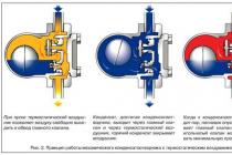
Rice. 1. Main types:
a) - mechanical (float); b) - thermodynamic; c) - thermostatic
There are three fundamentally different types: mechanical, thermostatic and thermodynamic.
Operating principle mechanical based on the density difference between steam and condensate. The valve is actuated by a ball or inverted cup float. Mechanical steam traps provide continuous condensate removal at steam temperature, so this type of device is well suited for heat exchangers with large heat exchange surfaces and intensive formation of large volumes of condensate.
Thermostatic steam traps determine the temperature difference between steam and condensate. The sensitive element and actuator in this case is a thermostat. Before the condensate can be discharged, it must be cooled to a temperature below the dry saturated steam temperature.
Based on the operating principle thermodynamic steam trap lies the difference between the velocities of steam and condensate in the gap between the disk and the seat. When condensate passes through, due to low speed, the disc rises and allows condensate to pass through. As steam enters the thermodynamic steam trap, the velocity increases, resulting in a drop in static pressure, and the disc sinks onto the seat. The steam above the disc, due to the larger contact area, keeps the disc in the closed position. As the steam condenses, the pressure over the disc drops and the disc begins to rise again, letting the condensate through.
 Table 1. Types of steam traps
 Table 2. Comparison of steam traps and their types
Steam trap selection
For the correct selection of the nominal diameter of the steam trap you must first determine the inlet pressure, see fig. 3.
If the steam trap is installed downstream of a steam consuming plant, the inlet pressure is 15% lower than the inlet pressure of the installation.
For an approximate calculation of back pressure, we assume that each meter of pipeline rise is 0.11 bar of back pressure.
Differential pressure = Inlet pressure - Back pressure.
The amount of condensate can be calculated using the technical documentation of the manufacturer of steam-consuming equipment, taking into account the safety factor for condensate consumption. On the main steam pipelines, in heat exchangers and similar equipment, the throughput margin must be set to 2.5 - 3 times the calculated one. In other cases, the stock is 1.5 - 2 times larger.
After calculating the safety factor for condensate flow, the diameter of the steam trap is selected according to the diagram
throughput (see Fig. 2) provided by the manufacturer.
Below are AYVAZ SK-51 throughput diagrams as an example (data and recommendations provided by AYVAZ UKRAINE).
 Rice. 2. Capacity Chart SK-51 (1/2”-3/4”-1”)
Chart example (See Fig. 2): The steam trap is set to a condensate flow rate of 180 kg/h.
The condensate is removed from the heat exchanger at a pressure of 6 bar and a back pressure of 0.2 bar. Pressure drop 6 - 0.2 = 5.8 bar.
Condensate consumption 180 x 3 = 540 kg/h.
Safety factor: 3.
To drain 540 kg/h of condensate at a drop of 5.8 bar, on the blue line in the diagram marked with the number 10 (the throughput in this case is 700 kg/h), we select a steam trap with a diameter of 1” (DN25). The number 10 indicates the size of the exhaust valve opening. As can be seen from the diagram (Fig. 2), steam traps with a diameter of 1/2” and 3/4” cannot be selected in this case, because their condensate capacity is lower than required.
Use of flash steam energy
When water is heated at constant pressure, its temperature and heat content increase. This continues until the water boils. Reaching the boiling point, the temperature of the water does not change until the water has completely turned into steam. And since it is required to use the thermal energy of the steam as much as possible, steam traps are used, see Fig. 3.
 Rice. 3. Use of condensate and flash steam for heat exchange
Condensate has the same temperature at a given pressure as steam. When the condensate after the steam trap enters the atmospheric pressure zone, it instantly boils up and part of it evaporates, because. the temperature of the condensate is higher than the boiling point of water at atmospheric pressure.
The steam that is formed when the condensate boils is called flash steam.
Those. it is steam that is formed as a result of condensate entering the atmosphere or medium with low pressure and temperature.
Calculation of the amount of flash steam:
where:
Ek
: Enthalpy of condensate entering the steam trap at a given pressure (kJ/kg).
Ev
: Enthalpy of condensate downstream of the trap at atmospheric pressure or at the current pressure in the condensate line (kJ/kg).
St
: The latent heat of vaporization at atmospheric pressure or at the current pressure in the condensate line (kJ/kg) of the pipeline is 0.11 bar backpressure.
As can be seen, the greater the pressure difference, the greater the amount of flash steam produced. The type of steam trap used also affects the amount of condensate produced. Mechanical drain condensate with a temperature close to the saturation temperature of the steam. While thermostatic - remove condensate with a temperature much lower than the saturation temperature, while the amount of steam of secondary boiling is reduced.
When sampling flash steam, it is necessary to take into account that:
- To produce even a small amount of flash steam, a large amount of condensate is required. Pay special attention to the capacity of the steam trap. It should also be taken into account that the pressure after the control valves is usually low.
- The scope of application should correspond to that for the use of flash steam. The amount of flash steam should be equal to or slightly more than what is required to ensure the technical process.
- The flash steam area should not be located far from the equipment from which high temperature condensate is discharged.
An example of calculating the amount of flash steam in a system where condensate is removed immediately after its formation, see below.
Let's take the data from the table of saturated steam: at a pressure of 8 bar, 170.5°C, condensate enthalpy = 720.94 kJ/kg. At atmospheric pressure, 100°C, condensate enthalpy = 419.00 kJ/kg. The enthalpy difference is 301.94 kJ/kg. Latent heat of vaporization at atmospheric pressure = 2258 kJ/kg. Then the amount of flash steam will be:
 Thus, if the steam consumption in the system is 1000 kg, then the amount of flash steam will be 134 kg.
Features of installation of steam traps
When installing a steam trap, make sure that the arrow on its body corresponds to the flow direction, see Fig. 4, a).
Float type steam traps must be installed strictly horizontally. Some, in a special design, can be installed vertically. The steam inlet to such steam traps must be from the bottom side, see Fig. 4, b).
Steam traps must be located below the steam line connection to the equipment. Otherwise, the equipment may be flooded. In cases where the installation of condensate traps in this way is not possible, it is necessary to organize a forced condensate drain, see Fig. 4, c).
Thermodynamic steam traps work in any position. However, the horizontal position is more preferable for installation, see Figure 4, d).
Rice. 4. Proper installation of the steam trap
Steam traps must not be installed one behind the other under any circumstances. Otherwise, the second one will create pressure that will adversely affect the operation of the first one, which is already mounted, see fig. 5a).
Filters installed upstream of steam traps must be turned to the left or right. Otherwise, condensate will accumulate at the bottom of the filter, which can lead to water hammer, see fig. 5 B).
 Rice. 5. Installation of a steam trap in the system
The right choice and use of equipment from the manufacturer AYVAZ is an effective way to increase the level of energy saving in steam systems.
More important articles and news in the Telegram channel AW-therm. Subscribe!
Viewed: 4 718The calculation formula is as follows:
where:
D - pipeline diameter, mm
Q - flow rate, m3/h
v - allowable flow velocity in m/s
The specific volume of saturated steam at a pressure of 10 bar is 0.194 m3/kg, which means that the volumetric flow rate of 1000 kg/h of saturated steam at 10 bar will be 1000x0.194=194 m3/h. The specific volume of superheated steam at 10 bar and a temperature of 300°C is 0.2579 m3/kg, and the volume flow with the same amount of steam will already be 258 m3/h. Thus, it can be argued that the same pipeline is not suitable for transporting both saturated and superheated steam.
Here are some examples of pipeline calculations for different media:
1. Wednesday - water. Let's make a calculation at a volume flow rate of 120 m3/h and a flow velocity v=2 m/s.
D= =146 mm.
That is, a pipeline with a nominal diameter of DN 150 is required.
2. Medium - saturated steam. Let's make a calculation for the following parameters: volume flow - 2000 kg / h, pressure - 10 bar at a flow rate of 15 m / s. In accordance with the specific volume of saturated steam at a pressure of 10 bar is 0.194 m3/h.
D= ![]() = 96 mm.
= 96 mm.
That is, a pipeline with a nominal diameter of DN 100 is required.
3. Medium - superheated steam. Let's make a calculation for the following parameters: volume flow - 2000 kg/h, pressure - 10 bar at a flow rate of 15 m/s. The specific volume of superheated steam at a given pressure and temperature, for example, 250°C, is 0.2326 m3/h.
D= ![]() =105 mm.
=105 mm.
That is, a pipeline with a nominal diameter of DN 125 is required.
4. Medium - condensate. In this case, the calculation of the diameter of the pipeline (condensate pipeline) has a peculiarity that must be taken into account in the calculations, namely: it is necessary to take into account the share of steam from unloading. Condensate, passing through the steam trap, and getting into the condensate pipeline, is unloaded (that is, condensed) in it.
The share of steam from unloading is determined by the following formula:
Share of steam from unloading = ![]() , where
, where
h1 - enthalpy of condensate in front of the steam trap;
h2 - enthalpy of condensate in the condensate network at the corresponding pressure;
r is the heat of vaporization at the corresponding pressure in the condensate network.
According to a simplified formula, the share of steam from unloading is determined as the temperature difference before and after the steam trap x 0.2.
The formula for calculating the diameter of the condensate line will look like this:
D=  , where
DR - share of condensate discharge
Q - amount of condensate, kg/h
v” - specific volume, m3/kg
Let's calculate the condensate pipeline for the following initial values: steam consumption - 2000 kg/h with pressure - 12 bar (enthalpy h'=798 kJ/kg), unloaded to a pressure of 6 bar (enthalpy h'=670 kJ/kg, specific volume v” =0.316 m3/kg and heat of condensation r=2085 kJ/kg), flow velocity 10 m/s.
Share of steam from unloading = ![]() = 6,14 %
= 6,14 %
The amount of unloaded steam will be: 2000 x 0.0614=123 kg/h or
123x0.316= 39 m3/h
D=  = 37 mm.
That is, a pipeline with a nominal diameter of DN 40 is required.
PERMISSIBLE FLOW RATE
The flow rate is an equally important indicator in the calculation of pipelines. When determining the flow rate, the following factors must be taken into account:
Pressure loss. At high flow rates, smaller pipe diameters can be selected, but there is a significant pressure loss.
pipeline cost. A low flow rate will result in larger piping diameters being selected.
Noise. A high flow rate is accompanied by an increased noise effect.
Wear. High flow rates (especially in the case of condensate) lead to pipe erosion.
As a rule, the main cause of problems with the removal of condensate is precisely the underestimated diameter of the pipelines and the wrong selection of condensate traps.
After the steam trap, particles of condensate, moving through the pipeline at the speed of steam from unloading, reach the turn, hit the wall of the turn, and accumulate at the turn. After that, they are pushed along the pipelines at high speed, leading to their erosion. Experience shows that 75% of leaks in condensate lines occur in pipe bends.
In order to reduce the likely occurrence of erosion and its negative impact, it is necessary to take a flow velocity of about 10 m/s for systems with float steam traps for calculation, and 6 -8 m/s for systems with other types of steam traps. When calculating condensate pipelines in which there is no steam from unloading, it is very important to make calculations, as for water pipes with a flow rate of 1.5 - 2 m / s, and in the rest, take into account the share of steam from unloading.
The table below shows the flow rates for some media:
Wednesday | Options | Flow rate m/s |
Steam | up to 3 bar | 10-15 |
3 -10 bar | 15-20 |
|
10 - 40 bar | 20-40 |
|
Condensate | Pipeline filled with condensate | |
Condensato- steam mixture | 6-10 |
|
Feed water | suction line | 0,5-1 |
Supply pipeline |