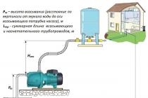
created pressure;
performance;
electric motor power.
In this article, we will focus on a simplified calculation of head and performance.

The head generated by the pump must be composed of three important values:
1. When determining the required pump head, you need to remember that 1 meter of vertical pressure is approximately equal to 10 meters of horizontal pressure (in fact, many factors affect this ratio).
If it is written in the characteristics of the pump that the maximum head at zero performance reaches H max \u003d 48 meters , it means that vertically this pump will raise water to a height of 48 meters, or at zero lifting height, it will be able to deliver water about 480 meters horizontally (but the water will flow out in a weak trickle).
For example, you are installing a pump in the basement of a house or garage, which is 3 meters below ground level. Before the entrance of the water supply system to a one-story house, where water is supplied - 20 meters. This means that you need a pump with a head over 5 meters at a certain capacity:
H max \u003d 3 + 20/10 \u003d 5 meters .
But for normal operation of the water supply system, you need a pump with a certain head and capacity.
You ask: "Why at a certain performance?"
Answer: “You need the water from the hose or tap not to drip (and the maximum pressure is indicated on the pump at zero capacity, or vice versa), but to flow out with a capacity sufficient to remove water from the container. For domestic purposes, the pump performance is sufficient if the maximum head created by the pump (specified in the pump specifications) exceeds the calculated one by 3 meters. In this case, 8 meters. Again, do not forget that in some cases a head margin is required, which determines the pump performance, that is, the head should be significantly higher.
More accurate calculations of the pressure and performance of the pump, depending on the complexity of the pipeline system, the distance of water movement and the lift height, is determined by special diagrams, tables, or for difficult operating conditions of the water supply system, the most complex calculations are made, in which all parameters and characteristics of the system are taken into account with a certain degree of error.
2. The pressure recommended (required) at the point of consumption, as a rule, for all household consumers should be from 1.5 to 3.0 bar ( bar ) which corresponds to pressure from 15 to 30 meters H waste \u003d (15 ... 30) m.
3. The design head of the pump to the main points of consumption (for example, before the entrance of the water supply system to a one-story house):
N calc = H geo + H waste + H sweat
Where: N calc - design head created by the pump, m ;
H geo - geodetic height of water rise (vertical distance from the pump installation site to the highest-located consumer), m .
H waste - the pressure that must be created at the most distant point and highest consumption point, m .
H sweat - total hydraulic resistance along the entire length L tr suction and discharge pipelines (total head loss). **
* Suction height
The higher the water temperature, the lower the suction lift, and practically at + 65 degrees Celsius ( ° C) water intake becomes impossible.
Typically, the geometric suction head for is no more than 5, 7 meters and only for some types of pumps it reaches 9 meters.
** Accurate calculation of total hydraulic head losses along the entire length L tr pipelines and elements of installation equipment, elements of control automation, etc. extremely difficult - you have to take into account a very large number of factors.
For extremely approximate and simplified calculations, it is often enough to assume that for a horizontal section of a pipeline 100 meters long, the difference between the pressure at the inlet and outlet, taking into account the pressure losses, we conventionally assume a pressure drop of 10 m, which corresponds to a pressure drop of about 1 bar ( bar ) .
Simplified example of the calculation at the level of "two palbtsev "(taken as a basis).
a) Let's give an example or a problem:
The length of the pipe is 25 meters in height (from the dynamic water level to the farthest point of consumption). How much pump head do we need to reach the point of consumption?
The solution is very simple - we need a head equal to the height from the dynamic water level to the point of consumption , i.e 25 meters!
Note! The task states that the water must reach the point of consumption, and not pour out of the pipe like a fountain.
b) If you want to understand: "How to find the pressure value so that at the outlet at the point of consumption the water comes out as a fountain?" - let's solve the following problem.
The distance from the water level to the point of consumption is 35 meters high. What pump head do we need for the water to come out of the pipe like a fountain or at least exceed the height of the consumption point? The solution is also very simple! The pump head must be over 35 meters!
A task: The vertical length of the pipe from the water level to the point of consumption is 35 meters. What pump head do we need in order to create a head equal to 30 meters at the pipe outlet (or in other words at the point of consumption)?
Decision: The pump must have a head equal to 65 meters! This figure is obtained by adding two data: 35 m (vertical length of the pipe from the water level to the point of consumption) + 30 m (standard head recommended at the point of consumption - see details above) \u003d 65 meters .
4. Loss of created pressure - pressure loss, pressure drop between the inlet and outlet of a hydraulic system structural element, which include pipelines, fittings, electric pumps, control automation elements, etc.
The head loss generated by the pump when pumping liquid depends on:
the material from which the pipeline elements are made;
geometric characteristics of pipelines (lengths, diameters, bending angles of the used adapters, bends, etc.);
the presence of valves, filters (both coarse and fine), bends, fixtures and other auxiliary devices;
the actual technical condition of the hydraulic system, including the degree of roughness of the internal surfaces;
viscosity of the pumped liquid.
The loss of the generated head can be roughly calculated from the tables, which indicate the values \u200b\u200bof the reduction in head, expressed in meters of water column.
Considering that:
10 m.w.st. (10 meters of water column) \u003d 1 bar ( bar ) \u003d 100000 Pa ( Pa ) \u003d 100 kPa ( kPa )
It is necessary for any calculations to bring all values \u200b\u200bto one unit of measurement.
An example of calculating the losses of the created pressure ( h P ) .
The pressure in the water supply system has noticeably decreased (decreased) - we will try to find the reason - we will justify the need to replace pipes, pipeline elements or an existing pump, and then change the inner diameter (hence, increase the pipe cross-section) and the type of material from which the pipes of the water supply system are made, or the existing one pump.
Initial data:
1) The water supply system was assembled from galvanized steel pipes with an inner diameter d 1 \u003d 25 mm .
2) To pump liquid in the water supply system, a conventional centrifugal pump with a capacity Q \u003d 4.0 m 3 / h .
3) The total length of the pipelines is L \u003d 100 m .
4) For clarity and simplification of the example, we do not take into account the number and angles of bends of the used adapters, bends - we consider only the pressure losses along the length of the straight pipeline (which has little to do with real life, since in reality any water supply system consists of all kinds of bends, adapters , fittings, various elements of stop valves, including taps, valves; we deliberately keep silent about the actual state of the inner walls of steel pipes after a certain period!).
Question:
How much will the created pressure change if, during the reconstruction of the water supply system, instead of dismantled steel pipes, PVC pipes with an inner diameter will be used
d 2 \u003d 38 mm?
Decision:
1) According to the following table of head losses, we determine the head loss with a length L \u003d 100 m pipeline and performance Q \u003d 4.0 m 3 / h for PVC pipes with an inner diameter d 1 \u003d 25 mm.
The head loss is h 1 \u003d 21.5 m ( m.w.c.) , which corresponds to a decrease in pressure by the value:
∆ P 1 \u003d 2.15 bar ( bar ).
2) At the bottom of the table in the note it is indicated that the obtained value of the pressure loss for galvanized steel pipes must be multiplied by the correction factor k = 1,5. As a result, we get the value of the pressure loss:
h 2 \u003d 21.5 m × 1.5 \u003d 32.25 m ( m.w.c.) , which approximately corresponds to a decrease in pressure by the value: ∆ P 2 \u003d 3.23 bar ( bar ). (This is the result on a conventional pipeline 100 meters long!)
3) According to the loss table for PVC pipes with a diameter d 2 \u003d 38 mm and length L \u003d 100 m at performance Q \u003d 4.0 m 3 / h define head loss equal to h 3 = 2.9 mWC, which corresponds to a pressure drop of 0.29 bar ( bar ).
4) After replacing galvanized steel pipes with inner diameter d 1 \u003d 25 mm for PVC pipes with an inner diameter d 2 \u003d 38 mm , with the same length of the pipeline L \u003d 100 m and with the same performance Q \u003d 4.0 m 3 / h conditional pump (according to the condition of the problem, the pump was not changed!) received lower head and pressure losses:
h \u003d h 2 - h 3 \u003d 32.25 - 2.9 \u003d 29.35 m (m.w.c.) ; or ∆P \u003d ∆P 2 - ∆P 1 \u003d 3.23 - 0.29 \u003d 2.94 bar (bar)
Conclusion: let's change the pipes for the water supply system, not the pump (the pump is not "to blame")!
Table for calculating head losses (in meters of water column) for PVC and polypropylene pipes, depending on the capacity, length and diameter of the pipeline. (All numerical values \u200b\u200bof the head losses given in the table are experimentally established, since there are no simple formulas for calculating the losses!)

Table for calculating head losses (in meters of water column) for steel pipes when pumping waste water, depending on the capacity, length and diameter of the pipeline. (All numerical values \u200b\u200bof the head losses given in the table are experimentally established, since there are no simple formulas for calculating the losses!)

The calculation of performance should be made according to two main values:
1. Consumption at the point of consumption.
2. Loss of productivity along the length of the pipeline from the pump to the point of consumption.
As for the consumption of water consumption, then there is approximately a ready-made digital standard.
Approximate consumption of water from consumers:
washbasin - 6 l / min;
toilet - 4 l / min;
dishwasher - 8 l / min;
shower - 10 l / min;
watering tap - 18 l / min;
washing machine - 10 l / min;
pool - 15 l / min;
watering lawns and flower beds requires up to 6 l / min of water per m 2, while the consumption also depends on the method of irrigation and the intensity of irrigation;
sauna or bath will require about 16 l / min.
In practice, the flow rate from one open tap is usually considered to be 10 liters / minute.
Take a bathroom faucet for example. According to experience, for comfortable use of the mixer, it is necessary that the outlet water flow is approximately equal to 15 liters per minute. We will take this value for the standard for the selection of the flow rate in this task.
But we have more than one draw-off point, then it is necessary to calculate the total flow for all consumption points. Accordingly, the consumption of all consumption points must be summed up and the maximum consumption indicator must be found.
Suppose we have two bathrooms and a kitchen. And let's imagine, for example, that in the first bathroom there is a shower, in the second there is a mixer and a washing machine, a tap is open in the kitchen and a dishwasher is running.
Summing up expenses from all consumption points 10 + 15 + 10 + 6 + 8 \u003d 49 liters per minute - got our expense from five main consumers.
We can select the required pump capacity, taking into account the approximate flow rate.
Important! When calculating the maximum capacity (volumetric flow) of the pump or when installing a pressure boosting pump, it is necessary to take a margin of at least (40 ... 50)% of the total maximum possible water consumption.
Important! When calculating the actual performance (volumetric flow) of the pump, it must be borne in mind that all consumers in the water supply system never work at the same time, respectively, the client can take a correction factor (safety factor for performance) equal to k zap \u003d 0.8 ... 0.9 \u003d (80 ... 90)% of the total maximum possible water consumption.
The performance of centrifugal pumps depends on the size of the impeller, its speed of rotation and the pressure of the liquid. With an increase in the liquid pressure, the pump performance decreases. With a free outlet of liquid from the discharge nozzle, the pump operates at maximum performance.
The operating characteristic of the pump (Fig. 24), obtained in a practical way, allows you to determine its performance at a given head.
Pump operating mode at optimum efficiency usually indicated in the pump's passport characteristics by the manufacturer.
The total liquid head created by a centrifugal pump can be roughly determined by the formula
where v is the circumferential speed of the impeller, m / s;
g - acceleration of gravity, m / sec 2;
n is the number of revolutions of the impeller per second;
R is the radius of the impeller, m.
The required power for the operation of a centrifugal pump can be determined by the formula
where Q is the capacity (flow) of the pump, m 3 / h;
Н - liquid head, m liquid. Art .;
p is the density of the pumped liquid, kg / m 3;
n - mechanical efficiency pump. For vane pumps n \u003d 0.10 ÷ 0.15, for disk pumps n \u003d 0.25 ÷ 0.30.
The calculated value of N is increased for the power reserve by 10-15%.

The performance of piston pumps is calculated by the formula
where F is the cross-sectional area of \u200b\u200bthe cylinder, m 2;
S - plunger stroke, m;
n is the number of revolutions of the crank per minute;
m is the number of cylinders;
n about - volumetric efficiency (n about \u003d 0.7 ÷ 0.75).
The power consumed by the plunger pump can be determined by the formula
![]()
where V is the volumetric capacity of the pump, m 3 / h;
p is the density of the liquid, kg / m 3;
Н - delivery head from the level of the suctioned liquid to the maximum height of the discharge pipeline, m;
h is the head required to overcome hydraulic resistance in the pipeline, m of water. Art .;
n М, - mechanical efficiency pump.
The volumetric capacity of rotary lobe pumps with external gearing is determined by the formula
![]()
where q is the volume between two adjacent gear teeth, m 3;
z is the number of gear teeth;
n is the number of gear revolutions per minute;
n about - volumetric efficiency (n about \u003d 0.7 ÷ 0.8).
The calculation of the pump for the well is made after the manufacture of the well, obtaining a passport for it. The documentation is issued by the specialists of the companies in which the service is ordered. It indicates the main parameters of the well - flow rate, mirror levels, filter design at the bottomhole. When filling out a well passport, professional equipment is used, which is many times superior to domestic pumps. Therefore, the user can safely choose any modification of the surface, submersible pump within the specified limits. Ideally, the performance of a borehole pump should be 5-10% less than that of the source of water intake. Figure: 1.
Figure 1. Scheme of the water intake source.
The calculation necessarily takes into account the characteristics:
- number of plumbing fixtures;
- their location diagram;
- family's daily fluid requirement;
- classification of the water treatment system used.
The calculations for submersible models are different from those for surface pumps. The best option for a downhole pump is a screw, vortex, centrifugal modification of equipment, allowing 40 g / l or 180 g / l of impurities, respectively. Vibration pumps sharply reduce the budget for water supply of the cottage, however, they have a low resource, fail with an abundance of sand.
Submersible pump capacity
To calculate the pump performance for a well, you need to know the flow rate. This indicator is the sum of the fluid consumption in several plumbing fixtures used simultaneously. For the convenience of calculations, the data are summarized in a table:

The calculation is made with a correction factor of 0.6-0.8, since the probability of simultaneous switching on of all consumers does not exceed 60-80%, respectively. The SNiP standards contain tables that facilitate calculations in non-standard situations (for example, a family of two living in a two-story mansion with bathrooms on each floor). They are based on actual operating experience. For example, if, when adding the total consumption for the available plumbing fixtures, 1 l / s is obtained, then in the table this value corresponds to a real consumption of 0.55 l / s. For a design flow rate of 5 l / s, 10 l / s, 15 l / s, practical values \u200b\u200bare 1.27 l / s, 1.78 l / s, 2.17 l / s, respectively.
Thus, a correction factor of 3.6 is added. In any case, the pump flow rate must exceed the family's water requirement.
Example for a submersible pump in a cottage
The calculation for a private cottage is made taking into account the available plumbing fixtures:

- toilet bowl - 0.1;
- washbasin - 0.09;
- kitchen sink - 0.15;
- water heater - 0.1;
- shower + mixer - 0.09.
The total consumption in the house will turn out to be 0.53 l every second, then a street watering tap (0.3 l / s) is added to it, which will be 0.83 l / s. This value in the table corresponds to the real characteristic of 0.48 l / s, which, after multiplying by the correction factor, gives 1.73 cubic meters per second. If the pump's passport indicates the capacity in l / h, then the calculations at the last stage change - the value from the table should be multiplied by 3600 seconds.
In a specific example of calculating a pump, the capacity of the equipment should exceed 1.73 cubic meters per hour. Comparing the characteristics of models from leading manufacturers, we find that for these operating conditions the following are suitable:

Figure 2. Pump modifications
- model 45 Pedrollo 4SR - 2 m 3 / h;
- pump 80 Aquatica 96 - 2 m 3 / h;
- modification 25Sprut 90QJD - 2 m 3 / h;
- options 63 Aquarius NVP, 32 Aquarius NVP - 1.8 m 3 / h.
The choice of the pump does not end there, since the next parameter is no less important for increasing the service life. Figure: 2.
Submersible pump head
The downhole pump is located inside the pumped liquid. Therefore, for these conditions, the height difference between the equipment and the water mirror is not taken into account. When selecting surface modifications (usually a pumping station), this parameter is present in the calculations without fail.
The pump head is calculated by adding three values:

- outflow head - taken 15-20 m;
- losses in the pipeline - the data are tabulated;
- height difference between plumbing fixtures, water mirror.
The pressure loss table takes into account friction in pipes from, fittings, shut-off valves, valves. The flow rate is taken into account, which is more influenced by the internal section of the pipes. Therefore, calculations will require an internal wiring diagram, an external water supply system.
An example of calculating the head of a submersible pump
Under the given conditions, the borehole pump is used in the following water supply system:
- well - 35 m from the surface;
- levels - dynamic 15 m, static 10 m;
- debit - 4 m 3 hourly;
- distance from the cottage - 30 m;
- the highest point of the plumbing fixture is 5 m (attic).

Borehole pump installation diagram and graphical calculation of head.
According to the SNiP, SanPiN standards, the well should be removed from the building by 50 - 20 m, from the septic tank of the autonomous drainage system by 15 m. At the first stage, the height difference is determined:
H 1 \u003d plumbing level + dynamic level \u003d 5 + 15 \u003d 20 m.
To calculate the pressure loss, it is necessary to consider the water supply diagram:
- from wells to the house, a 32 mm polypropylene pipe is usually used;
- internal wiring is performed with a 25 mm pipe made of the same material;
- the circuit contains one valve, two tees (watering + household line), three check valves, one 90 degree bend;
- according to the previous calculation, the productivity is 1.73 cubic meters, the value is rounded up to the tabular 1.8 m 3 / h;
- the losses will be 30 m, the head of the free spout is taken to be 20 m, the height difference is defined above, is 20 m, so the head of the equipment must exceed 70 m.
The performance of each pump for the well considered in the previous step meets the specified operating conditions. The well is equipped with any of them in accordance with the available budget. The calculations will not be complete without calculating the accumulator required to ensure the supply of water, increase the resource of pumping equipment, smooth out water hammer inside the water supply system.
Diaphragm tank for water supply
For a household well, accumulators of various designs, materials, volumes are used. The calculations will require the following data:

Well pumps can be submersible and surface.
- nominal performance of the equipment - 60% of the maximum pump flow;
- pressure difference - P 1 - P 2 (switch-on pressure is 10% lower than the maximum specified in the passport, the switch-off pressure is 10% higher than the minimum);
- hourly number of inclusions - usually declared by manufacturers 100;
- switch-on pressure;
- coefficient - 0.9 units.
To obtain the volume of the membrane tank, you must:
- add the switch-on pressure, unit, pressure difference;
- multiply the resulting number by 1000, nominal flow;
- divide result by 4, maximum number of hourly starts, pressure difference, coefficient.
Manufacturers produce storage tanks of standard volumes, after calculating the required volume of the accumulator, it remains to choose the closest size with a 15% margin. The well is usually used in winter / summer water supply schemes for seasonal, intermittent residences. At each departure of the owners, the system is conserved, water is drained from the circuits through the drain line. The volume of the well is not enough for this, an additional reservoir buried in the ground increases operating costs. Therefore, a budget option is used in the form of a well.
Surface pumps are self-priming structures, they are used at shallow depths of 8-12 m. Water from an artesian well of 100-200 m can be raised only with professional equipment, which is too expensive for a family's budget. They use ejectors, wells satisfy the needs of entire cottage villages.
The performance of surface self-priming equipment is calculated in the same way as in the previous case. When calculating the pressure, the relative position of the water supply elements is taken into account:
- the pump can be located in the basement, in the utility room of the lower floor, in the technical underground, in the caisson at the wellhead;
- the accumulator is mounted at any level.
The calculations are similar to those for submersible pumps, but a subtraction from the head H b is added. This is the value of losses depending on the height of the tank - the difference in the heights of the accumulator, the water intake mirror. If we take the calculation option for a two-story cottage with the following characteristics:
- distance of the source from the building 20 m;
- lifting water from a depth of 6 m with a pump pipe;
- water intake mirror at a depth of 4 m;
- the total depth of the well is 10 m;
- the location of the pump in the caisson;
- bathroom height 5 m.
The height difference will be 5 m.With a scheme with two 90 degree taps, a pair of valves, three tees, three check valves, a similar pipe section (25 mm internal, 32 mm external), the pump will need a capacity of 3 cubic meters every minute. The head loss will be 37 m, the head of the spout is 20 m, the height of the source is 6 m. Thus, for an autonomous water supply system, a pump with a head of more than 70 m is required, which is a rarity for models of most manufacturers. In this case, the rational solution would be to use the submersible modification after a similar calculation.
To organize the water supply of a private house before installing pumping equipment, first of all, it is necessary to calculate its parameters. In this case, it is necessary to take into account the technical characteristics of the source, the distance to the consumer and the volume of water intake. A homeowner who independently installs a water supply line to a house does not need to calculate a pump for a well using complex formulas - for this, online calculators posted on the network are intended.
Figure: 1 Online calculator for determining the volume of delivery - appearance
Their significant drawback is the approximateness of the results obtained - many important parameters affecting the final result do not appear in the input data. Almost all online calculators calculate only one of the parameters: lift height, performance or the required pressure in the line, the rest of the data has to be determined in other ways. Another problem is choosing an accurate and reliable calculator from the many options available on the net. Therefore, the most correct solution to the question of how to calculate a pump for a well is to calculate its parameters using formulas using loss tables and use calculators as an aid to check the correctness of calculations.
![]()
Figure: 2 Online calculator for calculating a pump for water supply
What must be considered when calculating an electric water pump
The need to accurately determine the parameters of pumping equipment is very important when ensuring a constant water supply to a private house. If the capacity is calculated inaccurately, the water intake devices will pump out an insufficient amount of water - this will require its replacement and, accordingly, additional costs. The use of pumping equipment with a large margin of parameters can lead to even greater financial losses: in addition to unjustified purchase costs, during operation the electric pump will operate with low efficiency, consuming an unreasonably large amount of electricity.

Figure: 3 Wiring diagram for submersible borehole pump
When calculating an electric water pump for a water supply system, it is necessary to take into account the following parameters of the water intake tank and the water main.
Intake source depth
It is necessary to know the depth of the borehole or well bottom when determining the flow rate of the source, this is important from a practical point of view - the found distance from the surface to the bottom will allow you to optimally select a pump with the required immersion depth and lift height in this range.

Figure: 4 Static and dynamic levels
Static level
The distance from the water surface of the source to the surface plays a role in determining the lift height and immersion depth of the pump. The static level is determined when there is no water intake and the source is in a quiet state for at least an hour or, for higher accuracy, a day. The indicator has a seasonal dependence and falls in the spring flood; therefore, its highest level should be determined in dry summer weather.
Dynamic level
The distance from the water surface to the surface when the electric pump is running is a dynamic level; it differs significantly from the static level in shallow, low-rate Abyssinian or sandy wells with low pressure. In artesian springs, where the water pressure is significantly higher and is balanced by a high column, the dynamic level with household intake volumes is usually equal to the static one.
Knowing the dynamic level is especially important when choosing the immersion depth of the electric pump - in the off state it will experience a load from a liquid column with a height from the immersion depth under the dynamic level mirror (1 - 2 m) to the static level surface.
Consumption
The calculation of the pump performance depends on the number of people living and the connected points and is calculated using the calculators of water intake for household appliances and plumbing fixtures. It should be borne in mind that consumption should not exceed the flow rate of the source.

Fig. 5 Table of water consumption for household appliances
Borehole pipe or well diameter
This indicator mainly affects the choice of pump model. In narrow, shallow Abyssinian wells, it is impossible to install a deep submersible electric pump, the liquid is lifted by centrifugal surface aggregates with a lowering into the source of the suction water intake pipe. Standard submersible electric centrifugal pumps have a diameter of about 4 inches and are designed to be immersed in bore holes with a diameter of at least 100 mm. For some high-performance submersible models with a diameter of 6 inches, well pipes with a width of at least 150 mm are required. The well rings must be wide enough to accommodate a well electric pump with a surface float switch located on the water surface up to 300 mm. from the central axis of the pump.
Water quality
The liquid that the electric pump lifts to the surface has a different quality depending on the type of water intake source. In budgetary Abyssinian species with a depth of no more than 8 m, due to their low weight and design features, the suction holes are located in the thickness of the aquifer. The well provides clean water; centrifugal or vortex types of electric pumps can be used for its intake. Deeper sand wells, due to their considerable mass, are located on the sandy or clay bottom of the aquifer. Depending on the structure of the bottom, pressure, distance of the inlet of the pressure pipe, the liquid being lifted in sandy wells has a different degree of purity. Deep-seated centrifugal electric pumps are used for taking pure water from sources or with a low content of impurities; a more turbid liquid can be lifted by means of a screw-type device. Due to the harmful effect on the walls of the casing pipes, low productivity, short continuous suction time and low efficiency, vibration models are not used to provide constant water supply to a private house. When calculating the pump power, the calculator must take into account the hydraulic losses in the water filters.
The casing pipes of artesian wells are installed on a solid limestone bottom, the raised water in this case is the cleanest with a very high iron content; vortex or centrifugal electric pumps can be used for intake.
Distance from home to source
When calculating the required pressure, vertical meters are converted into horizontal ones; this ratio depends on the diameter and material of the pipeline, which affect its hydraulic resistance.
Water supply pressure
The electric pump must not only deliver water to the consumer, but also provide the required pressure in the system. This indicator affects the strength of the water jet in the tap, and ensures the operation of the automation, set to a certain range. First of all, this applies to the pressure switch and idle, at low pressure, the automation will not turn off the electric pump, its excessive value, in addition to everyday inconveniences, can lead to a rapid failure of the water supply system components.
Calculation of the main parameters of the water supply system

Figure: 6 Losses in the water supply system depending on the diameter of the pipes
When choosing and calculating an electric borehole pump for a water supply system, it is necessary, taking into account the above data, to correctly select its following parameters.
Type of electric pump according to the principle of operation. As mentioned above, the borehole pump is selected according to the principle of operation individually for each type of water intake tank.
Immersion depth... The value in the pump passport data should not be lower than the difference between the dynamic and static level.
Delivery volume... The calculation of productivity is carried out taking into account the number of people living in the house, consuming household appliances (washing machines and dishwashers) and water intake points. Showers and bathrooms, toilets, bidets, sinks and sinks are taken into account.
It is often necessary to care for the plants on the site, so the water supply must take into account the cost of watering. You can calculate the power and delivery volume using tables or by making calculations with a calculator, summing up all the indicators.
It is not at all necessary to count all the points of water intake in the house in order to determine the pump power, you can use the tables to determine the consumption according to daily rates, while the average indicator lies within 200 liters. for one person.

Figure: 7 Daily intake rates
Lifting height... The main parameter of the pump, which must be accurately calculated. The pressure indicated in the passport data must perform the following functions:
- The rise of liquid from the water intake tank to a height to the surface from a distance of 1 - 2 m below the dynamic level.
- Horizontal delivery to the consumer. When calculating, take 1 m. Of the vertical column equal to 10 m. Horizontal plastic pipes with a diameter of 1 inch. With a decrease in the diameter of the pipes, the flow drops significantly; pipes of a smaller diameter are rarely used in the plumbing system. It is also unprofitable to use steel pipes, the hydraulic resistance of which is greater than plastic ones and the flow is reduced by 0.7 times.
- Operating pressure. The pump must provide a system pressure of 1.4 to 2.8 bar as standard. (1 bar. Is approximately equal to 1 atm. Or 10 m. Vertical water column).

Figure: 8 Hydraulic loss table

H tr - the desired value for the deep pump.
H geo - the height of rise and the length of the horizontal section in vertical meters of the water column.
H losses - the sum of losses in the water supply system, set according to tables or calculations. These losses are associated with the friction of the fluid against the pipe surface, as well as the drop in speed in the elbows and tees.
H free - head to create working pressure in the system. This value should be taken in the range of 15 - 30 m.
Calculation of performance and lifting height is the main task when choosing pumping equipment. The first parameter can be set according to consumption rates per person, when calculating the pressure, the length of the vertical section, the length of the horizontal line and the pressure in the system are summed up, converted to meters of water column. Calculation of power in this case is not required, it will depend on the performance of the submersible electric pump and the height of the liquid rise.
For the selection of a centrifugal pump, a graphical dependence of the pressure on the flow is used, which is individual for each model and is given in the manufacturers' catalogs.
The method of selecting a centrifugal pump depends on the tasks assigned to it. To select a booster pump, they are set by the flow rate and a perpendicular is drawn from the abscissa axis to the pump characteristic curve, the resulting operating point will determine the head at a given flow rate.
The circulation pump is selected by superimposing on the pump characteristic, the hydraulic characteristic of the circulation ring, which reflects the dependence of the head loss on the flowing flow. The duty point will be at the intersection of the pump and circulating ring characteristics.
If several models correspond to the specified parameters, a less powerful pump operating in a mode with higher efficiency is chosen. When choosing a centrifugal pump for a network with a variable water flow, it is better to give preference to a model with a flatter pressure characteristic and a wide flow range.
Noise performance often becomes the predominant parameter when selecting pumps for installation in residential buildings. In such cases, it is recommended to select a pump with a lower power electric motor and a speed of no more than 1500 rpm.
Calculation of a centrifugal pump
The calculation of a centrifugal pump consists in determining two parameters necessary for the operation of the system - supply and head. The approach to calculating the specified parameters should be different depending on the installation scheme.
Calculation of the booster pump for the water supply system, it is performed according to the load of the hour of maximum water consumption, and the pressure is determined by the difference between the set pressure at the inlet to the water supply system and the pressure at the inlet of the water supply system.
The pressure at the inlet to the water supply system is equal to the sum of the excess pressure at the upper draw-off point, the height of the water column from the pump to the upper point and the head loss in the section from the booster pump to the upper point. Excessive pressure at the upper draw-off point is usually taken as 5-10 mWC.
Calculation of the make-up pump for a heating system, they are performed based on the maximum permissible filling time of the system and its capacity. The filling time of the heating system is usually taken no more than 2 hours. The head of the make-up pump is determined by the difference between the pump cut-off pressure (system full) and the pressure at the connection of the make-up line.
Calculation of the circulation pump for the heating system, they are performed based on the heat load and the calculated temperature schedule. The pump flow is proportional to the heat load and inversely proportional to the calculated temperature difference in the supply and return pipelines. The head of the circulation pump is determined only by the hydraulic resistance of the heating system, which must be indicated in the project.
Cavitation
Cavitation is the formation of vapor bubbles in the thickness of a moving liquid when the hydrostatic pressure decreases and the collapse of these bubbles in the thickness where the hydrostatic pressure increases.
In centrifugal pumps, cavitation occurs at the impeller inlet edge, at the location with the highest flow rate and minimum hydrostatic pressure. The collapse of a vapor bubble occurs during its complete condensation, while at the point of collapse, a sharp increase in pressure occurs up to hundreds of atmospheres. If at the moment of collapse the bubble was on the surface of the impeller or blade, then the impact falls on this surface, which causes metal erosion. The surface of the metal exposed to cavitation erosion is chipped.
Cavitation in the pump is accompanied by a sharp noise, crackling, vibration and, which is especially important, a drop in pressure, power, flow and efficiency. There are no materials that are absolutely resistant to cavitation destruction; therefore, the operation of the pump in the cavitation mode is not allowed.
The minimum inlet pressure to a centrifugal pump is called NPSH and is indicated by the pump manufacturer in the datasheet.
Let's analyze an absolutely reliable example from practice:
We have a plot with one one-story house and a bathhouse. Number of residents - 3 people. The house has a sink, toilet, washbasin. The bath has a shower and another washbasin. Separate branch for watering. A coarse filter with a cell of 200 microns is provided. The accumulator is located in the basement at a level of 1.5 meters below the floor level of the 1st floor. An Aquarius pump is needed for a well, the flow rate of which is unknown.
Mirror of water - 6 meters from the surface of the earth
The total depth of the well is 9 meters.
The distance from the well to the house (accumulator) is 15 meters.
The distance from the house to the bathhouse is 8 meters.
A plastic pipe with an outer diameter of 25 mm (inner diameter 20.5 mm) was laid on the site.
Due to the small column of water in the well (only 3 meters), we install the pump at 0.6 meters from the bottom (according to the passport, the Aquarius pump allows installation at the level of 0.4 meters from the bottom of the well, but we make a minimum stock).
If the well has not been serviced for a long time and is silted up, the pump can supply turbid water in this case, and you will have to raise the pump higher.
Calculation of the required water consumption:
The required water consumption is determined as the sum of the productivity of all draw-off points, taking into account the likelihood of their simultaneous use.
Secondary water consumption rates for plumbing fixtures:
Washbasin - 0.12 l / s
Toilet bowl - 0.1 l / s
Washing - 0.12 l / s
Shower - 0.2 l / s
Watering tap - 0.3 l / s
Maximum theoretical water demand (without irrigation) \u003d 0.66 l / s (2 x 0.12 + 0.2 + 0.12 + 0.1), which corresponds to 2.37 m³ / h.
In practice, they cannot use all the plumbing fixtures at the same time. The coefficient of simultaneous use of devices for a private residential building with 3 residents can be taken equal to 0.7.
This factor is only valid for individual residential buildings. In apartment buildings and office premises, the required consumption is calculated according to peak loads during the hours or days of the highest water consumption, taking into account different groups of consumers according to much more complex formulas.
Q \u003d 2.37 m³ / h x 0.7 \u003d 1.65 m³ / h
In our case, this corresponds to the simultaneous use of a shower, washbasin and sink. Watering is supposed to be carried out with a separate branch (a watering tap requires 1 m³ / h of water), but in our case, even during watering, it will be possible to comfortably use a washbasin, a toilet bowl and a sink. When the shower is also turned on, the pressure will certainly drop below the calculated one, although at the same time all consumers will be provided with water, since all Aquarius pumps can freely operate in the range of up to 3 m³ / h.
Note that the resulting flow rate of about 1.6 m³ / h just corresponds to the well-known water flow for a family of 2-3 people.
Calculation of the required head of a submersible pump for a well:
The required head of the Aquarius pump is the sum of the total geodetic head, pressure losses in pipelines, taking into account local losses and the final required pressure at the points of draw-off.
Geodetic head - (in our case) the total height difference from the pump installation site to the gyroaccumulator installation site. Taking into account that the pump stands 0.6 meters above the bottom of the well, and the accumulator is located 1.5 meters below the ground, the geodetic head will be:
L1 \u003d (9-0.6) + (-1.5) \u003d 6.9 meters
In fact, it would be correct to calculate the total height difference from the location of the uppermost consumer to the dynamic water level in the well. But according to the condition of the problem, we do not know the dynamic level (and this is exactly what happens in the overwhelming majority of cases with wells), and the difference in height between the uppermost consumer (we have everything on the ground floor) and the hydraulic accumulator is only 1.5 meters. Therefore, we are calculating not from the dynamic level of water in the well, but from the place of installation of the pump, assuming the worst case that the water can drop to this level during operation. We insist that this is permissible for calculations of water supply from such wells. Moreover, the water column is only 3 meters.
Head loss in pipelines:
The total length of pipes from the installation site of the Aquarius pump to the accumulator:
L tr \u003d (9-0.6) + 15 \u003d 23.4 meters
Let's use the head loss table.
| Head loss in meters, per 100 meters of straight section of the pipeline | |||||||||||
| Liquid consumption | External diameter of the plastic pipeline, mm | ||||||||||
| m³ / h | l / min | l / s | 25 | 32 | 40 | 50 | 63 | 75 | 90 | 110 | 125 |
| 0,6 | 10 | 0,16 | 1,8 | 0,66 | 0,27 | 0,085 | |||||
| 0,9 | 15 | 0,25 | 4,0 | 1,14 | 0,6 | 0,18 | 0,63 | ||||
| 1,2 | 20 | 0,33 | 6,4 | 2,2 | 0,9 | 0,28 | 0,11 | ||||
| 1,5 | 25 | 0,42 | 10,0 | 3,5 | 1,4 | 0,43 | 0,17 | 0,074 | |||
| 1,8 | 30 | 0,50 | 13,0 | 4,6 | 1,9 | 0,57 | 0,22 | 0,092 | |||
| 2,1 | 35 | 0,58 | 16,0 | 6,0 | 2,0 | 0,7 | 0,27 | 0,12 | |||
| 2,4 | 40 | 0,67 | 22,0 | 7,5 | 3,3 | 0,93 | 0,35 | 0,16 | 0,063 | ||
| 3,0 | 50 | 0,83 | 37,0 | 11,0 | 4,8 | 1,4 | 0,5 | 0,22 | 0,09 | ||
| 3,6 | 60 | 1,00 | 43,0 | 15,0 | 6,5 | 1,9 | 0,7 | 0,32 | 0,13 | 0,05 | |
| 4,2 | 70 | 1,12 | 50 | 18,0 | 8,0 | 2,5 | 0,83 | 0,38 | 0,17 | 0,068 | |
| 4,8 | 80 | 1,33 | 25,0 | 10,5 | 3,0 | 1,2 | 0,5 | 0,22 | 0,084 | ||
| 5,4 | 90 | 1,5 | 30,0 | 12,0 | 3,5 | 1,3 | 0,57 | 0,26 | 0,092 | 0,05 | |
| 6,0 | 100 | 1,67 | 39,0 | 16,0 | 4,6 | 1,8 | 0,73 | 0,3 | 0,12 | 0,07 | |
For a pipe with an outer diameter of 25 mm, at a flow rate of 1.65 m³ / h, the losses will amount to 11.5 meters (for a pipe 100 meters long). The pressure loss in our case will be:
H pot. Long \u003d 0.234 x 11.5 \u003d 2.7 meters
In the section from the pump to the accumulator there will be four pipeline turns at an angle of 90 °, two gate valves, three tees and one check valve.
To calculate local losses, we will use the table below.
| Head loss in knees, gate valves, bottom and non-return valves, in cm | ||||||||
| Water speed, m / s | Knee with an angle, degrees | Gate valve | Check valve | Tee | ||||
| 30 | 40 | 60 | 80 | 90 | ||||
| 0,4 | 0,43 | 0,52 | 0,71 | 1 | 1,2 | 0,23 | 31 | 16 |
| 0,5 | 0,67 | 0,81 | 1,1 | 1,6 | 1,9 | 0,37 | 32 | 16 |
| 0,6 | 0,97 | 1,2 | 1,6 | 2,3 | 2,8 | 0,52 | 32 | 17 |
| 0,7 | 1,35 | 1,65 | 2,2 | 3,2 | 3,9 | 0,7 | 32 | 17 |
| 0,8 | 1,7 | 2,1 | 2,8 | 4 | 4,8 | 0,95 | 33 | 18 |
| 0,9 | 2,2 | 2,7 | 3,6 | 5,2 | 6,2 | 1,2 | 34 | 18 |
| 1,0 | 2,7 | 3,3 | 4,5 | 6,4 | 7,6 | 1,4 | 35 | 19 |
| 1,5 | 6,0 | 7,3 | 10,0 | 14 | 17 | 3,3 | 40 | 24 |
| 2,0 | 11,0 | 14,0 | 18,0 | 26 | 31 | 5,8 | 48 | 30 |
| 2,5 | 17,0 | 21,0 | 28,0 | 40 | 48 | 9,1 | 58 | 39 |
| 3,0 | 25,0 | 30,0 | 41 | 60 | 70 | 13 | 71 | 50 |
In our case, the fluid flow rate will be 1.4 m / s (V \u003d Q / S x 3600, where Q \u003d 1.65 m³ / h, S \u003d (Π x d2) / 4 \u003d 0.00032684 m², with an inner diameter pipeline d \u003d 20.4 mm; passport data of our pipeline).
Let's summarize certain types of local losses:
4 x 16 (90 degree bends) + 2 x 3 (gate valves) + 3 x 23 (tees) + 1 x 39 (reverse valve) \u003d 178 cm \u003d 1.78 meters
Total total head losses were:
H pot \u003d 5.5 m (2.7 meters of losses along the length of the pipe + 2.8 meters of local losses).
Pressure at draw-off points:
We will select the pump for the well to ensure the design pressure in the house at 2.5 bar (when the pump is running). At the same time, in any operating mode, the pressure in the house and the bath should not fall below 2.0 bar (provided by the pressure switch settings).
Why exactly 2.5 bar? This is the average calculated value for comfortable water use. For example, in a city apartment, the average pressure in the cold water network is about 2.0-3.5 bar (depending on the location).
The head losses in the section from the accumulator to the consumers in the house will be as follows:
1.5 m - the difference in height between the installation level of the accumulator and the consumers (according to the condition of the problem).
2.5 m - pressure loss on the coarse filter; his passport details.
1 m - other losses along the length of the pipe and local losses (it is impractical to make an accurate calculation due to the minimum distances of the pipeline and simple geometry).
In total, the losses in the section from the accumulator to consumers on the first floor of the house will be:
H pot.d \u003d 1.5 m +2.5 m +1 m \u003d 5 m (0.5 bar)
Thus, in order to maintain the pressure in the house at 2.5 bar, the pressure in the accumulator must be 0.5 bar higher, i.e. it must be 3.0 bar.
The pressure in the bath will be lower than the pressure in the accumulator by the amount of losses along the length of the pipe from the house to the bath + the value of local losses + 1.5 meters (the difference in height between the place where the accumulator is installed and the consumers in the bath). Losses along the length of the pipe and local losses can be neglected due to the small length of the pipes, low flow rate (there are only two draw-off points in the bath) and simple geometry. The pressure drop by 2.5-3 meters (0.25-0.3 bar) is not so significant and will not affect the comfort of using water. With a different geometry of the site (for example, when the bath is at a distance of 30-40 meters from the house), it would be necessary to take this into account in the general calculation and compensate for it by increasing the pressure in the accumulator.
The pressure switch settings can be assigned already at this stage of the calculation, taking the average pressure in the accumulator at the level obtained above 3.0 bar, set the pressure switch as follows:
Pump activation - 2.5 bar.
Pump off - 3.5 bar.
The air pressure in the accumulator is 2.3 bar.
Let's dwell here in a little more detail. The air pressure should be lower than the pump start pressure by about 5-10%. This is a general rule for adjusting the air pressure in accumulators of any manufacturer. This value must be checked regularly, for example once every three months, and, if changes, brought back to normal. This will directly affect the service life of the accumulator membrane and even the pump.
The total required head of the Aquarius pump when supplying water from a well:
H \u003d 6.9 m (geodetic head) + 5.5 m (friction head loss along the pipe length + local losses)
+ 30 m (3 bar - average design pressure in the accumulator) \u003d 42.4 meters.
Those. our pump must provide Q \u003d 1.65 m³ / h at H \u003d 42.4 m.
Choosing a specific submersible pump for a well:
We look at the hydraulic characteristics of Promelectro pumps and choose the Aquarius BTsPE 0.5-40 U pump, which, at a flow rate of 1.65 m³ / h, provides 42 meters of head. The difference in pressure of 0.4 meters (42.4m - 42m) does not play any role in this case, since we took all the values \u200b\u200bfor flow and pressure with a margin and the calculation error is comparable to this value. The operating point is close to the nominal operating mode, which is very good (1.8 m³ / h is the maximum efficiency mode for all pumps Aquarius BTsPE 0.5). At the same time, the pump has a maximum head (at zero flow) of 60 meters, which guarantees the provision of the calculated shutdown pressure of the pump, set by us at 3.5 bar (35 m + 6.9 m + 5.5 m \u003d 47.4 m
It would be possible, "as always with a small margin," to choose the next pump in the line Aquarius BTsPE 0.5-50 U, but one would have to overpay both for the pump itself and for a large power consumption (about 140 W), and each day. And the pump we have chosen provides all the specified hydraulic characteristics.
After starting the pump, we measure the flow rate for irrigation (which was launched by a separate branch and implies the highest pump flow rate), and with the help of the valve, by closing it, we adjust the pump flow rate at a level of no more than 1.0-1.2 m³ / h. Since irrigation can take a long time, it is necessary to correlate this flow rate with the flow rate of the well, which in most cases does not exceed 0.8-1.2 m³ / h (and since in our case it is generally unknown, at the initial stage of operation, the water level in the well will need to be monitored).
It should be noted that if in our case the total length of the pipes were higher (for example, about 60-70 meters), or over time it would be planned to install a serious water treatment system that could cause additional pressure losses of 1-1.5 bar, then certainly it would be necessary to foresee this in advance and choose a more powerful pump (such as Aquarius BTsPE 0.5-50 U).
On the other hand, for our well, installing a smaller BTsPE 0.5-32 U pump would force us to change the pressure switch settings, since this pump could not provide a head of 47.4 meters (the head required to turn off the pump - see above) ... The maximum rated head of the Aquarius BTsPE 0.5-32 U pump is 47 meters (this is at a nominal supply voltage of 220 V, which is not always the case). The relay settings would have to be changed: switch-on pressure - 2.0 bar, switch-off pressure 3.0 bar. With such installations, the pressure in the bath at the moment the pump is turned on would drop below 1.5 bar, which in practice is not always comfortable. Therefore, the choice of the BTsPE 0.5-40 U pump for our well is optimal.
Not knowing the correct answer initially, the chosen example turned out to be very successful, since it allows you to pay attention to various nuances when choosing a submersible pump for a well, which is much more important for the buyer than the ability to accurately choose a submersible pump yourself. In the end, this free procedure must be entrusted to a professional, at least in order to test oneself.
To organize the water supply of a private house before installing pumping equipment, first of all, it is necessary to calculate its parameters. In this case, it is necessary to take into account the technical characteristics of the source, the distance to the consumer and the volume of water intake. A homeowner who independently installs a water supply line to a house does not need to calculate a pump for a well using complex formulas - online calculators posted on the network are designed for this.
Figure: 1 Online calculator for determining the volume of delivery - appearance
Their significant drawback is the approximation of the results obtained - many important parameters affecting the final result do not appear in the input data. Almost all online calculators calculate only one of the parameters: lift height, performance or the required pressure in the line, the rest of the data has to be determined in other ways. Another problem is choosing an accurate and reliable calculator from the many options available on the net. Therefore, the most correct solution to the question of how to calculate a pump for a well is to calculate its parameters using formulas using loss tables and use calculators as an aid to check the correctness of calculations.
 Figure: 2 Online calculator for calculating a pump for water supply
 The need to accurately determine the parameters of pumping equipment is very important when ensuring a constant water supply to a private house. If the capacity is not calculated accurately, the water intake devices will pump out an insufficient amount of water - this will require its replacement and, accordingly, additional costs. The use of pumping equipment with a large margin of parameters can lead to even greater financial losses: in addition to unjustified purchase costs, during operation the electric pump will operate with low efficiency, consuming an unreasonably large amount of electricity.
 Figure: 3 Wiring diagram for submersible borehole pump
 When calculating an electric water pump for a water supply system, it is necessary to take into account the following parameters of the water intake tank and the water main.
Intake source depth
It is necessary to know the depth of the borehole or well bottom when determining the flow rate of the source, it is important from a practical point of view - the distance from the surface to the bottom will allow you to optimally select a pump with the required immersion depth and lift height in this range.
 Figure: 4 Static and dynamic levels
 Static level
The distance from the water surface of the source to the surface plays a role in determining the lift height and immersion depth of the pump. The static level is determined when there is no water intake and the source is in a quiet state for at least an hour or, for higher accuracy, a day. The indicator has a seasonal dependence and falls in the spring flood; therefore, its highest level should be determined in dry summer weather.
Dynamic level
The distance from the water surface to the surface when the electric pump is running is a dynamic level; it differs significantly from the static level in shallow, low-rate Abyssinian or sandy wells with low pressure. In artesian springs, where the water pressure is significantly higher and is balanced by a high column, the dynamic level with household intake volumes is usually equal to the static one.
Knowing the dynamic level is especially important when choosing the immersion depth of the electric pump - in the off state it will experience a load from a liquid column with a height from the immersion depth under the dynamic level mirror (1 - 2 m) to the static level surface.
Consumption
The calculation of the pump performance depends on the number of people living and the connected points and is calculated using the calculators of water intake for household appliances and plumbing fixtures. It should be borne in mind that consumption should not exceed the flow rate of the source.
 Fig. 5 Table of water consumption for household appliances
Borehole pipe or well diameter
This indicator mainly affects the choice of pump model. In narrow, shallow Abyssinian wells, it is impossible to install a deep submersible electric pump, the liquid is lifted by centrifugal surface aggregates with a lowering into the source of the suction water intake pipe. Standard submersible electric centrifugal pumps have a diameter of about 4 inches and are designed to be immersed in bore holes with a diameter of at least 100 mm. For some high-performance submersible models with a diameter of 6 inches, well pipes with a width of at least 150 mm are required. The well rings must be wide enough to accommodate a well electric pump with a surface float switch located on the water surface up to 300 mm. from the central axis of the pump.
Water quality
The liquid that the electric pump lifts to the surface has a different quality depending on the type of water intake source. In budgetary Abyssinian species with a depth of no more than 8 m, due to their low weight and design features, the suction holes are located in the thickness of the aquifer. The well provides clean water; centrifugal or vortex types of electric pumps can be used for its intake. Deeper sand wells, due to their considerable mass, are located on the sandy or clay bottom of the aquifer. Depending on the structure of the bottom, pressure, distance of the inlet of the pressure pipe, the liquid being lifted in sandy wells has a different degree of purity. Deep-seated centrifugal electric pumps are used for taking pure water from sources or with a low content of impurities; a more turbid liquid can be lifted by means of a screw-type device. Due to the harmful effect on the walls of the casing pipes, low productivity, short continuous suction time and low efficiency, vibration models are not used to provide constant water supply to a private house. When calculating the pump power, the calculator must take into account the hydraulic losses in the water filters.
The casing pipes of artesian wells are installed on a solid limestone bottom, the raised water in this case is the cleanest with a very high iron content; vortex or centrifugal electric pumps can be used for intake.
Distance from home to source
When calculating the required pressure, vertical meters are converted into horizontal ones; this ratio depends on the diameter and material of the pipeline, which affect its hydraulic resistance.
Water supply pressure
The electric pump must not only deliver water to the consumer, but also provide the required pressure in the system. This indicator affects the strength of the water jet in the tap, and ensures the operation of the automation, set to a certain range. First of all, this applies to the pressure switch and idle, at low pressure, the automation will not turn off the electric pump, its excessive value, in addition to everyday inconveniences, can lead to a rapid failure of the water supply system components.
Calculation of the main parameters of the water supply system
 Figure: 6 Losses in the water supply system depending on the diameter of the pipes
 When choosing and calculating an electric borehole pump for a water supply system, it is necessary, taking into account the above data, to correctly select its following parameters.
Type of electric pump according to the principle of operation. As mentioned above, the borehole pump is selected according to the principle of operation individually for each type of water intake tank.
Immersion depth... The value in the pump passport data should not be lower than the difference between the dynamic and static level.
Delivery volume... The calculation of productivity is carried out taking into account the number of people living in the house, consuming household appliances (washing machines and dishwashers) and water intake points. Showers and bathrooms, toilets, bidets, sinks and sinks are taken into account.
It is often necessary to care for the plants on the site, so the water supply must take into account the cost of watering. You can calculate the power and delivery volume using tables or by making calculations with a calculator, summing up all the indicators.
It is not at all necessary to count all the points of water intake in the house in order to determine the pump power, you can use the tables to determine the consumption according to daily rates, while the average indicator lies within 200 liters. for one person.
 Figure: 7 Daily intake rates
 Lifting height... The main parameter of the pump, which must be accurately calculated. The pressure indicated in the passport data must perform the following functions:
- The rise of liquid from the water intake tank to a height to the surface from a distance of 1 - 2 m below the dynamic level.
- Horizontal delivery to the consumer. When calculating, take 1 m. Of the vertical column equal to 10 m. Horizontal plastic pipes with a diameter of 1 inch. With a decrease in the diameter of the pipes, the flow drops significantly; pipes of a smaller diameter are rarely used in the plumbing system. It is also unprofitable to use steel pipes, the hydraulic resistance of which is greater than plastic ones and the flow is reduced by 0.7 times.
- Operating pressure. The pump must provide a system pressure of 1.4 to 2.8 bar as standard. (1 bar. Is approximately equal to 1 atm. Or 10 m. Vertical water column).
 Figure: 8 Hydraulic loss table

H tr - the desired value for the deep pump.
H geo - the height of rise and the length of the horizontal section in vertical meters of the water column.
H losses - the sum of losses in the water supply system, set according to tables or calculations. These losses are associated with the friction of the fluid against the pipe surface, as well as the drop in speed in the elbows and tees.
H free - head to create working pressure in the system. This value should be taken in the range of 15 - 30 m.
Calculation of performance and lifting height is the main task when choosing pumping equipment. The first parameter can be set according to consumption rates per person, when calculating the pressure, the length of the vertical section, the length of the horizontal line and the pressure in the system are summed up, converted to meters of water column. Calculation of power in this case is not required, it will depend on the performance of the submersible electric pump and the height of the liquid rise.
The reason is not in the quality of equipment, but in the fact that the project and selection are carried out not by professional designers, but by the owners of private organizations. For example, a “layman” cannot know that the engine of a pump selected with a large margin can burn out if the pump is not brought into the operating range during installation and setup of the system. How to avoid such mistakes when choosing a pump?
DEFINITION OF PUMP PARAMETERS
In all cases, for the correct choice of the pump, first of all, it is necessary to determine its operating parameters - flow Q and pressure H... The required water consumption is determined from the total productivity of all water points of the facility, taking into account the likelihood of their simultaneous use.
In a simplified calculation, you can use the following water consumption rates for plumbing fixtures: washbasin - 60 l / h; toilet flush cistern - 83 l / h; kitchen sink - 500 l / h; bathroom - 300 l / h; watering tap - 1080 l / h (watering lawns and flower beds requires 3-6 m 3 of water per square meter, while the consumption also depends on the method of irrigation and the intensity of irrigation); a sauna or bath will require about 1000 l / h. The following formula is used to calculate the required pump head:
H tr \u003d H geo + S + H free
Where H geo - the height of the pipeline inlet in the building relative to the dynamic water level in the well (the numerical expression of the dynamic level must be present in the well certificate); S - the sum of the friction head losses in the pipeline and local resistances (fittings, fittings, filters, etc.); H free - the pressure that must be created at the entrance to the building, with the calculation of the provision at the most remote and high-located water draw-off point of pressure equal to 0.5 atm.
Well parameters are fundamentally important to the user, as they are used to calculate the required head and performance of the selected pump. In the well passport, the drillers must have work. Obviously, the calculation results will turn out to be incorrect if, when determining the dynamic level of the well, a pump of obviously lower power was used than is required to supply the facility in accordance with the consumer's requests.
And although it is difficult for the user to expect to quickly obtain an official passport for an artesian well (this is a state document that requires many permits and approvals), it is necessary to require the submission of detailed data on the well together with the act of work performed, incl. inquire about the power of the pump that pumped out water when determining the dynamic level. When concluding a contract for drilling work, you should pay attention to the availability of a license from the contractor.
At the end of the work, only serious companies always give the client a guarantee and a detailed well passport, where all the mentioned characteristics are clearly stated, as well as the diameter of the casing string, the list of soils passed, information about the trial pumping of the well, etc. - up to the recommended pump brand and installation depth.
Parameters required Q and H for additional equipment (jacuzzi, washer, sprinklers, "sprinklers", etc.) are indicated by the manufacturers. When installing water treatment filters, head losses (usually about 2 atm.) And water consumption for washing them are taken into account. For the pool, only the filling time is indicated.
EXAMPLE OF CALCULATION AND SELECTION OF A PUMP

The initial data are as follows:
It is required to provide water supply to a suburban area with a two-story cottage (a kitchen, two bathrooms and a shower with hydromassage require a flow rate of 1 m 3 / h and a pressure of 4-5 atm.), A garage, a house for service personnel (contains a bathroom), a bathhouse, a 45 m swimming pool 3, irrigation of the territory, water treatment system.
A family of four and two of the staff permanently reside on the site. A well 80 m deep was drilled for water supply of the site; casing diameter - 150 mm; static level - 46 m; dynamic level - 50 m; the flow rate measured during pumping is 3.5 m 3 / h.
The calculation is done like this:
Taking into account the water consumption rates (see the beginning of the article), we get the total consumption and pressure of consumers:
Q sum \u003d 500 + 3 x (60 + 83 + 500) + 1000 + 1000 + 2 x 1060 \u003d 6500 l / h \u003d 6.5 m3 / h,
H tr \u003d 50 + 8 + 20 + 2 +30 \u003d 110 m.
Due to the inexpediency of using all the taps at once, the required flow rate can be determined as 5 m 3 / h.,
The design data is satisfied, for example, a pump
Grundfos SP 5A (Q \u003d 5m 3 / h, H \u003d 120m).
This ensures sufficient consumption for the kitchen, one bathroom and watering. It is understood that the owners will not use the bathhouse and take a bathroom, take a shower and fill the pool at the same time as watering the area from both taps. To ensure pressure on irrigation installations and hydromassage, it is cheaper to use separate pumps - this will allow not to keep the entire water supply under high pressure and will make the operation of the submersible pump more stable, and the system flexible and independent (using an additional pump, you can always get high pressure at any point of analysis) ... The pool will fill up at night. In this case, with the help of a valve on the head, the pump should be "throttled" (create additional resistance) so that when working on filling the pool, the flow does not exceed the permissible - 6.5 m 3 / h.
IF PUMP OUTPUT IS OVERHANCED

Self-selection of a pump by a customer with excessive requirements for flow and head often leads to the selection of a pump with too high power. In the case of the initial data discussed above, such a pump can be Grundfos SP 14A-25. As already mentioned, when installing an overpowered model, complications are possible.
Firstly, since with such a choice, the nominal flow significantly exceeds the average water demand, the pump will operate in a frequent on / off mode. Manufacturers allow up to 30 pump starts per hour, but only for one hour per day, with a general limit of 60 cycles per day. In any case, frequent switching on negatively affects the service life of the electric motor and starting automatics. To avoid this, a large diaphragm tank will need to be installed.
Secondly, with an overestimated pump power, as a result, the water pressure at the entrance to the house will be overestimated. At the moment of starting such a pump, strong hydraulic shocks will inevitably occur. Some fittings may simply not be designed for such a pressure (dishwashers and washing machines, mixers); additional installation of pressure reducers will be required to reduce the pressure. Thirdly, during the filling of the pool, the pump will work on the "open pipe" without creating pressure.
In such conditions, there is a large flow of water at minimum pressure. The duty point of the pump shifts on the characteristic curve to the right, into an area that does not correspond to the working area of \u200b\u200bthe pump. The shaft power will be at its maximum and the engine will fail during prolonged operation.
The consequence of using a pump with an overestimated capacity will be a general rise in the cost of the entire system, caused by the use of more powerful electrical equipment, materials and fittings with a high permissible working pressure, an increase in the diameters of the pipeline and well, as well as an increase in the cost of water treatment. If the nominal pump flow exceeds the well flow rate, it is necessary to install additional dry running protection.
Choking and adjusting the pump will result in excessive energy consumption. In other words, while ensuring the possibility of the simultaneous use of all water points by installing an overpowered pump, the cost of the water supply system will increase. At the same time, the real water consumption will be much lower. Therefore, although the final choice will always remain with the customer, it is cheaper and more correct to choose a pump taking into account real needs and with the help of specialists.
It is possible to satisfy the user's requirements for the water supply system, subject to the rules for its installation and operation, by choosing the pump with a flat operating characteristic that is optimal in this situation.
For the water supply system from the example above, a Grundfos SP 8A-25 pump can be selected. In the zone of possible feeds (from 4 to 8 m 3 / h) for this model, the curve of the dependence of the pressure on the flow rate has a flat form, that is, at low water flow rates, there will not be too much pressure increase. At the same time, a certain allowable reserve when calculating water consumption will exclude the possibility of water shortages.
INSTALLATION OF SUBMERSIBLE PUMP

In any case, whichever pump is chosen, during installation it is necessary to adjust its operating point in all possible modes of operation. During commissioning, the supplied flow rate should be measured (determined by the filling rate of a container of a known volume, for example, a barrel), the generated pressure (as indicated by the pressure gauge on the tip) and the current consumed (measured with current tongs).
The obtained characteristics are checked against the pump passport data from the catalog. If the operating parameters are exceeded (a power reserve is provided, for example, for the subsequent installation of filters), it is necessary to close the valve at the exit from the well, create additional local resistance sufficient to set the correct operating point - the middle of the Q (H) characteristic.
The installation, as well as the selection of the pump, must be carried out by trained specialists, and the installation company must be licensed.
SUBMERSIBLE PUMP PROTECTION

Before choosing and purchasing a pump, it is necessary to obtain accurate information about the power supply voltage at the site. This is especially important when choosing an imported pump. All equipment supplied from abroad meets primarily the industrial standards of the country of origin. So, for German pumps, the permissible deviation of the mains voltage from the nominal is -10 ... + 6%.
Despite the built-in protections, the pump is not designed to operate from a network with a voltage below 200 V, all possible drawdowns and voltage surges will negatively affect the service life of the electric motor. Here it is necessary to provide for adjustable voltage protection as part of the control cabinet, and for three-phase pumps also against “non-phase” operating modes. It is not recommended to install powerful single-phase pumps. The starting current of a 2.2 kW motor can exceed the rated current by 4.4 times!
To stabilize the voltage within the operating range with such surges, a stabilizer with a fivefold power reserve will be required (more precisely, the choice will be made by the manufacturers of the stabilizer).
Sometimes it is cheaper for the user to provide a 380 V power supply at the facility than correct operation of a single-phase pump. According to statistics, about 85% of failures occur precisely with the electrical part of the pump. The main reason is the turn-to-turn closure of the stator windings due to overheating due to hydraulic overload, or when operating at low or abruptly changing voltage. Both can be avoided with proper overcurrent protection.
A conventional starter with overcurrent protection does this quite well, but some installers forget to adjust to the required current value. The result of such negligence is easy to calculate: you will have to pay for lifting the pump from the well, repairing it (the price of a new engine), for lowering the pump again and putting it into operation. The accumulated amount can easily exceed the cost of a new pump.
Glossary of terms
Pressure - excess pressure generated by the pump.Consumption - the volume of water by the transfer pump per unit of time.
Working point - the point of intersection of the pump characteristics curve Q (H) with the pipeline resistance characteristic SQ2, corresponding to the effective values \u200b\u200bof the pressure and flow rate when operating on a specific water supply system.
Throttling - creation of additional resistance on the pressure pipeline.
Performance characteristic - graph of the dependence of the operating parameters of the pump - head and flow rate Q (H).
Shaft power - the power consumed by the pump.
Static level - constant water level in the well.
Dynamic level - the water level in the well, established when pumping out the specific flow rate.
Well flow rate - stable water flow provided by the well.
Our Company offers a wide range of domestic and industrial submersible pumps: for water supply, irrigation and drainage. You can familiarize yourself with the assortment and technical characteristics on the website page.